Installation Instructions for B.A.S.I.S. Cylindrical Locks
BEST ACCESS SYSTEMS
Indianapolis, Indiana
Preparing the door and door jamb
2
1
Position template and mark drill points
Note:
If the door is a fabricated hollow metal door,
determine whether it is properly reinforced to support
the lock. If door reinforcement is not adequate, consult
the door manufacturer for information on proper
reinforcement. For dimensions for preparing metal
doors, see the
G01 and G02 Templates—Installation
Specifications for 93KG and 93KBV Cylindrical Locks
.
Note:
If the door is a LH or RH door, mark the inside of
the door. If the door is a LHRB or RHRB door, mark the
outside of the door.
For uncut doors and frames
1 Measure and mark the horizontal centerline of the
lever (the centerline for the chassis hole) on the door
and door jamb. Mark the vertical centerline of the door
edge.
Note:
The recommended height from the floor to the
centerline of the lock is 38
″
.
2 Fold
the
G05 Template—Installation Template for 93KG
and 93KBV Cylindrical Locks
on the dashed line and
carefully place it in position on the high side of the
door bevel.
Note:
For steel frame applications, align the template’s
horizontal centerline for the latch with the horizontal
centerline of the frame’s strike preparation.
3 Tape the template to the door.
4 Center punch the necessary drill points. Refer to the
instructions on the template.
For doors with standard cylindrical preparation
1 Fold
the
G05 Template—Installation Template for 93KG
and 93KBV Cylindrical Locks
on the dashed line.
Looking through the hole from the opposite side of
the door, align the template so that you see the
template outline of the 2 1/8
″
diameter chassis hole.
2 Tape the template to the door.
3 Center punch the necessary drill points. Refer to the
instructions on the template.
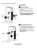
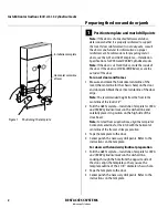
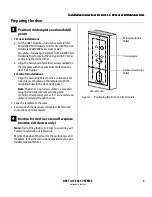
Figure 1
Positioning the template
Horizontal centerline
of lever
Installation template
Summary of Contents for B.A.S.I.S. V
Page 1: ...SERVICE MANUAL SERVICE MANUAL ...
Page 16: ...Figures xvi B A S I S V Service Manual ...
Page 48: ...Standard Functions and Parts 2 24 B A S I S V Service Manual ...
Page 66: ...Exit Hardware Trim Functions and Parts 3 18 B A S I S V Service Manual ...
Page 78: ...Shared Standard and Exit Hardware Trim Parts 4 12 B A S I S V Service Manual ...
Page 114: ...Servicing Standard Mortise Case Parts 6 20 B A S I S V Service Manual ...
Page 206: ...Servicing Exit Hardware Trim Escutcheon Parts 10 32 B A S I S V Service Manual ...
Page 238: ...Troubleshooting 12 12 B A S I S V Service Manual ...
Page 242: ...Lock History Event Types A 4 B A S I S V Service Manual ...
Page 244: ...Installation Instructions B 2 B A S I S V Service Manual ...


