Installation Instructions for B.A.S.I.S. EX Series Exit Hardware Trim
BEST ACCESS SYSTEMS
Indianapolis, Indiana
11
Installation Instructions for B.A.S.I.S. EX Series Exit Hardware Trim
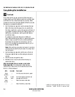
Completing the installation
17
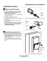
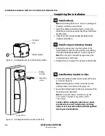
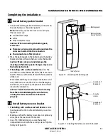
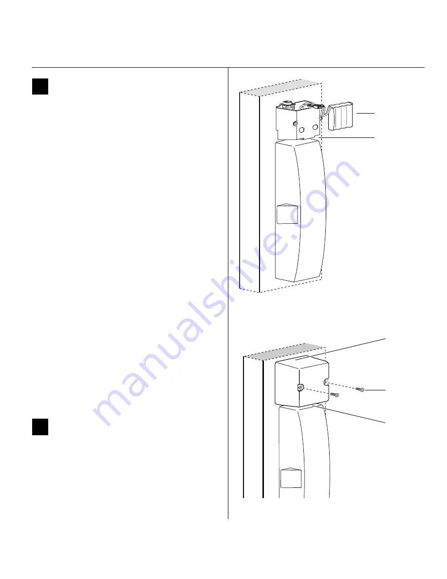
Install battery pack in bracket
1
Connect the battery pack to the battery connector on
the wire harness as shown in Figure 13.
Note:
The battery connection has 3 wires and 3 pins.
The wire colors are:
■
red with white stripe
■
white
■
black with white stripe.
Caution:
When connecting the battery pack,
make sure:
■
there are no loose wire connections where the
wires are inserted into the connectors
■
the connectors are firmly mated.
2
Place the battery pack in the holder inside the battery
bracket and dress the wire harness inside the bracket.
Caution:
Make sure you do not damage the
sleeving on the battery pack. Doing so may cause
the batteries to drain.
3
If installing with a surface rod device
, dress the
wire harness inside the bracket to the left of the rod so
that the harness will not interfere with the movement
of the rods.
We recommend that you loosely coil the harness and
use a cable tie to secure the coil. To avoid damaging
the harness, do not put any sharp bends in it or flex it
close to the connectors.
Caution:
Failure to dress the wire harness away
from the rod could damage the wire harness,
causing the lock’s electronics to not work
properly.
18
Install battery cover on bracket
1
If installing with a surface rod exit device
, remove
the knockouts for the rod from the battery cover. See
Figure 14.
2
Making sure that the battery cover does not pinch any
wires
, place the cover over the bracket.
3
Use a T15 TORX bit driver to secure the battery
compartment cover with the security screws. Tighten
firmly. See Figure 14.
Figure 13 Connecting the battery pack
Battery pack
Inside of door
Battery holder
(inside bracket)
Security
screws
Location of
knockout
Location of
knockout
Figure 14
Installing the battery cover on the bracket
Summary of Contents for B.A.S.I.S. V
Page 1: ...SERVICE MANUAL SERVICE MANUAL ...
Page 16: ...Figures xvi B A S I S V Service Manual ...
Page 48: ...Standard Functions and Parts 2 24 B A S I S V Service Manual ...
Page 66: ...Exit Hardware Trim Functions and Parts 3 18 B A S I S V Service Manual ...
Page 78: ...Shared Standard and Exit Hardware Trim Parts 4 12 B A S I S V Service Manual ...
Page 114: ...Servicing Standard Mortise Case Parts 6 20 B A S I S V Service Manual ...
Page 206: ...Servicing Exit Hardware Trim Escutcheon Parts 10 32 B A S I S V Service Manual ...
Page 238: ...Troubleshooting 12 12 B A S I S V Service Manual ...
Page 242: ...Lock History Event Types A 4 B A S I S V Service Manual ...
Page 244: ...Installation Instructions B 2 B A S I S V Service Manual ...


