Servicing Standard Mortise Trim Parts
B.A.S.I.S. V Service Manual
5–5
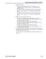
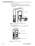
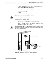
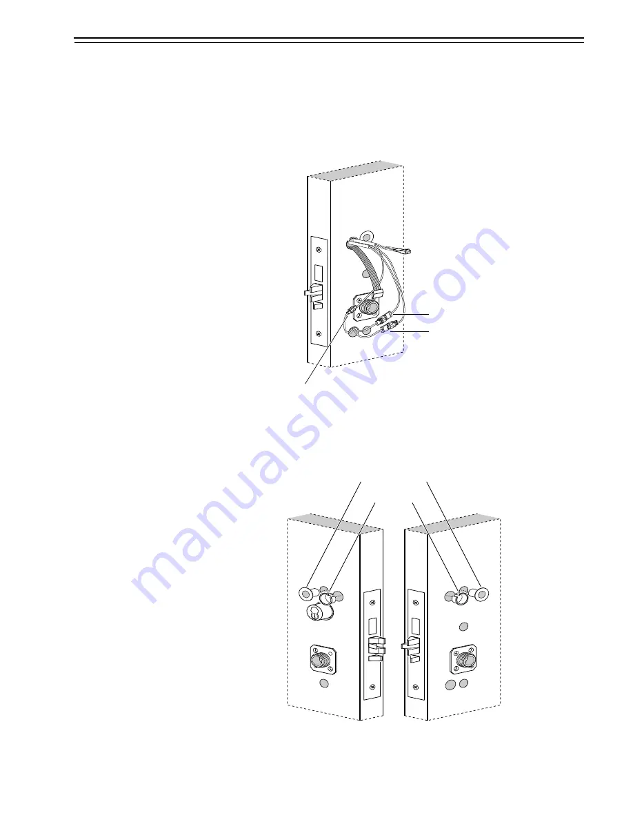
b. Remove the inside escutcheon from the door.
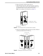
c. From the inside of the door, disconnect the motor connector,
the key override sensor connector (EV and FV functions), and
the deadbolt sensor connector (FV and LV functions).
Note:
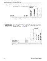
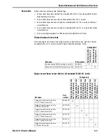
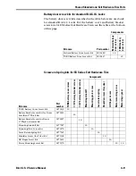
For a description of lock functions, see
page 2–2
.
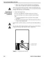
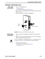
d. Remove the bushings and trim hole inserts (for locks with brass
escutcheons) from each side of the door.
Figure 5.5
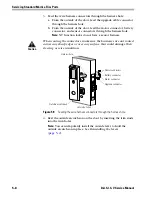
Disconnecting the motor connector and sensor connector
Motor connection
Key override sensor connector
Inside of door
Deadbolt sensor connector
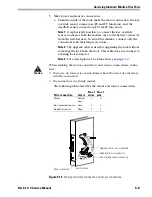
Figure 5.6
Removing the bushings and trim hole inserts
Trim hole inserts
Bushings
Summary of Contents for B.A.S.I.S. V
Page 1: ...SERVICE MANUAL SERVICE MANUAL ...
Page 16: ...Figures xvi B A S I S V Service Manual ...
Page 48: ...Standard Functions and Parts 2 24 B A S I S V Service Manual ...
Page 66: ...Exit Hardware Trim Functions and Parts 3 18 B A S I S V Service Manual ...
Page 78: ...Shared Standard and Exit Hardware Trim Parts 4 12 B A S I S V Service Manual ...
Page 114: ...Servicing Standard Mortise Case Parts 6 20 B A S I S V Service Manual ...
Page 206: ...Servicing Exit Hardware Trim Escutcheon Parts 10 32 B A S I S V Service Manual ...
Page 238: ...Troubleshooting 12 12 B A S I S V Service Manual ...
Page 242: ...Lock History Event Types A 4 B A S I S V Service Manual ...
Page 244: ...Installation Instructions B 2 B A S I S V Service Manual ...

