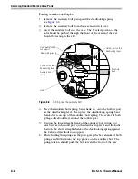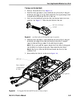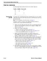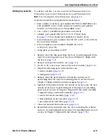
Servicing Standard Mortise Trim Parts
5–16
B.A.S.I.S. V Service Manual
S
ERVICING
THE
CYLINDER
Perform these steps for EV and FV function locks only.
Note:
For a description of lock functions, see
page 2–2
.
Removing the
cylinder
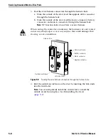
1. Remove the following parts:
■
levers (
page 5–2
)
■
inside and outside escutcheons (
page 5–3
)
■
core (
page 5–14
)
■
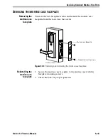
mortise case faceplate (
page 5–15
).
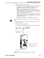
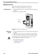
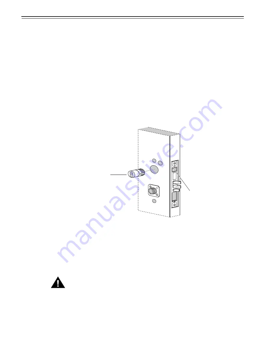
2. Loosen the cylinder set screw, found on the inside of the mortise
case.
3. Use a cylinder wrench (ED211) to turn the cylinder
counterclockwise until you can remove it.
Reinstalling the
cylinder
1. Use a cylinder wrench to thread the cylinder into the mortise case
so that the groove around the cylinder head is even with the door
surface.
Note:
Do not tighten the cylinder set screw until you reinstall the
outside escutcheon.
Caution
A malfunction can occur if the cylinder is threaded in too far.
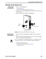
2. Reinstall the following parts:
■
core (
page 5–14
)
■
inside and outside escutcheons (
page 5–6
)
■
mortise case faceplate (
page 5–15
)
■
levers (
page 5–2
).
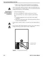
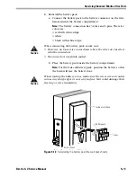
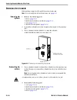
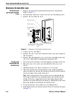
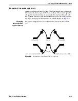
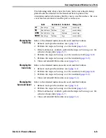
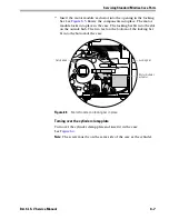
Figure 5.17
Removing and reinstalling the cylinder
Outside of door
Cylinder
Cylinder set screw
(inside mortise case)
Summary of Contents for B.A.S.I.S. V
Page 1: ...SERVICE MANUAL SERVICE MANUAL ...
Page 16: ...Figures xvi B A S I S V Service Manual ...
Page 48: ...Standard Functions and Parts 2 24 B A S I S V Service Manual ...
Page 66: ...Exit Hardware Trim Functions and Parts 3 18 B A S I S V Service Manual ...
Page 78: ...Shared Standard and Exit Hardware Trim Parts 4 12 B A S I S V Service Manual ...
Page 114: ...Servicing Standard Mortise Case Parts 6 20 B A S I S V Service Manual ...
Page 206: ...Servicing Exit Hardware Trim Escutcheon Parts 10 32 B A S I S V Service Manual ...
Page 238: ...Troubleshooting 12 12 B A S I S V Service Manual ...
Page 242: ...Lock History Event Types A 4 B A S I S V Service Manual ...
Page 244: ...Installation Instructions B 2 B A S I S V Service Manual ...


