40
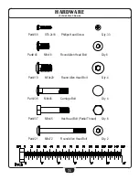
HARDWARE LIST
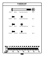
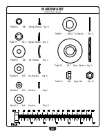
PART# QTY
DESCRIPTION
1 2 Starter
Batteries
(Type
AA)
Non-Warranty Item
2
2
Rear Leg End Cap
4 2 Round
Allen
Head
Bolt
M8x90
5 5 Washer
M10
(20OD
x
2t)
6 5 Nylon
Nut
M10
7
4
Plastic Bushing
16ID x 28OD x 16t
8 4 Bushing
10ID
x
18
ODx
11t
9
4
D-Washer
16.2ID x 28OD x 14t x B5
10
4 Round
Allen
Head
Bolt
M10x20
11
4 Spring
Washer
M10
12
10
Washer M8
(16OD
x
1.5t)
13
10
Nylon
Nut
M8
14
1 Left
Foot
Frame
15
1 Right
Foot
Frame
16
4 Cross
Pan
Head
Screw
M5x10
17
1 Right
Joint
Frame
18
2 Hex
Head
Bolt
M10x12
19
4 Bushing
12ID
x
32OD
x
15t
20
6
Arc Washer
M8 (19OD x 1.5t x R30)
21
2 Round
Allen
Head
Bolt
M8x72
22
2
Front Leg End Cap
25
6 Bushing
16ID
x
31OD
x23t
27
4 Phillips
Head
Screw
ST3.5
x
10
29
2 Foam
Grip
Upper
Handle
30
2 Round
End
Cap
Upper
Handle
31
1 Console
32
1 Console
Battery
Cover
33
1
Cross Head Pan Screw
M5x55
34
1 Arc
Washer
M5
35
4 Wave
Washer
M17
(23OD
x
0.3t)
36
4 Carriage
Bolt
M8x45
37
6 Hex
Head
Bolt
M8x45
38
2 Hex
Head
Bolt
M10x55
39
1 Left
Joint
Frame
40
2 Round
End
Cap
41
2 Handle
Bar
Foam
43
2
HR Cable Harness/HR Contact
44
8 Spring
Washer M8
45
8 Round
Allen
Head
Bolt
M8x16
48
1 Tension
Controller
50
1 Upper
Harness
51
2 Hex
Head
Bolt
M5
52
1 Lower
Tension
Cable
53
1 Lower
Harness
54
1 Left
Shroud
Part numbers are required when ordering parts.
Summary of Contents for BFCT1R
Page 1: ...OWNER S MANUAL BFCT1R v 051816 ...
Page 9: ...9 S T E P 1 Above shows STEP 1 assembled and completed ...
Page 11: ...11 S T E P 2 Above shows STEP 2 assembled and completed ...
Page 13: ...13 S T E P 3 Above shows STEP 3 assembled and completed ...
Page 15: ...15 S T E P 4 Above shows STEP 4 assembled and completed ...
Page 17: ...17 S T E P 5 Above shows STEP 5 assembled and completed ...
Page 19: ...19 S T E P 6 Above shows STEP 6 assembled and completed ...
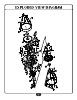
Page 42: ... 42 EXPLODED VIEW DIAGRAM ...
Page 43: ...43 EXPLODED VIEW DIAGRAM ...

