14
Be careful to assemble all components
in the sequence they are presented.
note:
Do not fully tighten bolts until the unit is completely assembled.
A.
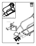
Slide Handle Bar (K) into Right Upright Post (F) and secure using:
two 59 (m5x10 phillips head bolt)
two 67 (m5.5 arc washer)
B.
Slide the remaining Handle Bar (K) into Left Upright Post (G) and secure
using:
two 59 (m5x10 phillips head bolt)
two 67 (m5.5 arc washer)
C.
Attach both Lower Handle Bars (J) to Main Frame (A) using:
four 48 (m10x25 round allen head bolt)
Six 65 (M10.5 flat washer)
two 70 (m10 nut)
s T e p
3
Summary of Contents for BFT50
Page 1: ...BFT50 O w n e r s M a n u a l v 091709...
Page 11: ...11 S T EP 1 Above shows STEP 1 assembled and completed...
Page 13: ...13 S T EP 2 Above shows STEP 2 assembled and completed...
Page 15: ...15 S T EP 3 Above shows STEP 3 assembled and completed...
Page 17: ...12 17 S T EP 4 Above shows STEP 4 assembled and completed...
Page 19: ...19 S T EP 5 Above shows STEP 5 assembled and completed...
Page 39: ...39 BFT50 Wiring Diagram...
Page 40: ...40 Exploded View Diagram...
Page 41: ...41 Exploded View Diagram...
Page 42: ...42 Notes...
Page 43: ...43 Notes...

