20
seTTing up YOur TreaDMill
pLacement in YOUR hOme
To make exercise a desirable daily activity for you, the treadmill should be placed in a com-
fortable and attractive setting. This treadmill is designed to use minimal floor space and to
fit nicely in your home.
Do not place or operate the treadmill outdoors.
Do not place the treadmill near water or in a high moisture content environment.
Make sure the power cord is not in the path of heavy traffic.
It is highly recommended to place a dedicated treadmill mat beneath your treadmill.
A dedicated mat provides superior stability and firmness for a proper workout.
Locate the treadmill at least 4 feet from walls or furniture.
Allow a safety area of 79” x 39” (2000mm x 1000mm) behind the treadmill
so that you can easily get on and off the treadmill and adjust the tension of the belt.
Occasionally, after extended use, you will find a fine black dust below your treadmill. This
is normal wear and DOES NOT mean there is anything wrong with your treadmill. This dust
can be easily removed with a vacuum cleaner. If you wish to prevent this dust from getting
on your floor or carpet, place a dedicated treadmill mat beneath your treadmill.
LeVeLing the BaSe
It is important that you place the treadmill on a firm level surface. If the ground is uneven,
you may level the treadmill with levelers located under the deck. Make sure the back of the
deck is not higher than the front. If adjustments are to be made, check to see if the leverage
feet, as shown below, touch the ground firmly. If there is a gap, turn the leverage foot coun-
terclockwise to eliminate the gap.
Make sure the running deck is level to the ground. If the deck is positioned so that you are
running downhill, it will cause premature damage to the electronic system
Adjustable Levellers
Summary of Contents for BFT50
Page 1: ...BFT50 O w n e r s M a n u a l v 091709...
Page 11: ...11 S T EP 1 Above shows STEP 1 assembled and completed...
Page 13: ...13 S T EP 2 Above shows STEP 2 assembled and completed...
Page 15: ...15 S T EP 3 Above shows STEP 3 assembled and completed...
Page 17: ...12 17 S T EP 4 Above shows STEP 4 assembled and completed...
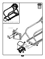
Page 19: ...19 S T EP 5 Above shows STEP 5 assembled and completed...
Page 39: ...39 BFT50 Wiring Diagram...
Page 40: ...40 Exploded View Diagram...
Page 41: ...41 Exploded View Diagram...
Page 42: ...42 Notes...
Page 43: ...43 Notes...


