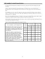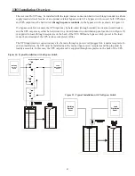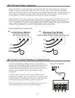
44
Input – Output
UPS Voltage
Output Wires
External
Bypass
Output
Isolation
System
Input – Output
System
Input – Output
Wiring Diagrams (Figure No.)
Output
Isolation
Wiring Diagrams (Figure No.)
220 – 220
L – N
Yes
No
26
16a – 22c
23
Yes
16a – 22a
230 – 230
L – N
Yes
No
26
16a – 22c
23
Yes
16a – 22a
240 – 240
L – N
Yes
No
26
16a – 22c
23
Yes
16a – 22a
208 – 208
L1 – L2
Yes
No
27
16a – 22e
24
Yes
16a – 22a
220 – 220
L1 – L2
Yes
No
27
16a – 22e
24
Yes
16a – 22a
230 – 230
L1 – L2
Yes
No
27
16a – 22e
24
Yes
16a – 22a
240 – 240
L1 – L2
Yes
No
27
16a – 22e
24
Yes
16a – 22a
110/220 – 110/220
L1, L2, N*
Yes
No
28
– – –
– – –
– – –
16b – 22b
120/208 – 120/208
L1, L2, N*
Yes
No
28
– – –
– – –
– – –
16b – 22b
120/240 – 120/240
L1, L2, N*
Yes
No
28
– – –
– – –
– – –
16b – 22b
100/200 – 100/200
L1, L2, N*
Yes
No
28
– – –
– – –
– – –
16b – 22b
127/220 – 127/220
L1, L2, N*
Yes
No
28
– – –
– – –
– – –
16b – 22b
220 – 110/220
L1, L2, N
Yes
– – –
– – –
16a – 22d
25
Yes
– – –
230 – 115/230
L1, L2, N
Yes
– – –
– – –
16a – 22d
25
Yes
– – –
240 – 120/240
230 – 115/230
220 – 110/220
127/220 – 127/220
100/200 – 100/200
120/240 – 120/240
120/208 – 120/208
110/220 – 110/220
240 – 240
230 – 230
220 – 220
208 – 208
240 – 240
230 – 230
220 – 220
240 – 120/240
L1, L2, N
L1, L2, N
L1, L2, N
L1, L2, N*
L1, L2, N*
L1, L2, N*
L1, L2, N*
L1, L2, N*
L1 – L2
L1 – L2
L1 – L2
L1 – L2
L – N
L – N
L – N
L1, L2, N
No
No
No
No
No
No
No
No
No
No
No
No
No
No
No
Yes
– – –
– – –
– – –
No
No
No
No
No
No
No
No
No
No
No
No
– – –
– – –
– – –
– – –
34
34
34
34
34
33
33
33
33
32
32
32
– – –
16a – 22d
16a – 22d
16a – 22d
– – –
– – –
– – –
– – –
– – –
16a – 22e
16a – 22e
16a – 22e
16a – 22e
16a – 22c
16a – 22c
16a – 22c
16a – 22d
31
31
31
– – –
– – –
– – –
– – –
– – –
30
30
30
30
29
29
29
25
Yes
Yes
Yes
– – –
– – –
– – –
– – –
– – –
Yes
Yes
Yes
Yes
Yes
Yes
Yes
Yes
– – –
– – –
– – –
16b – 22b
16b – 22b
16b – 22b
16b – 22b
16b – 22b
16a – 22a
16a – 22a
16a – 22a
16a – 22a
16a – 22a
16a – 22a
16a – 22a
– – –
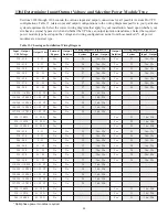
1304 Determining Input/Output Voltage and Selecting Power Module Type
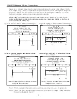
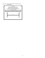
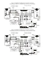
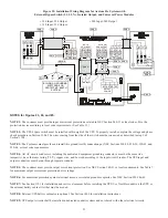
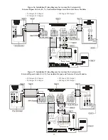
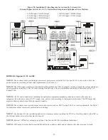
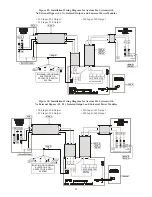
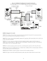
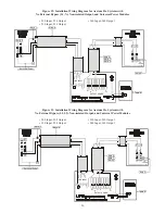
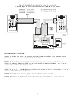
Sections 1305 through 1308 contain the various input and output connections for all possible Axxium Pro UPS
configurations. Table 13 relates input and output configurations to the wiring diagrams specific to your particular
system requirements. Select the correct wiring diagrams that apply to your installation, based upon whether your
site has an external bypass switch and whether the UPS has an output isolation transformer. Select the required
power module type based upon the voltage and wiring configuration; aside from those marked (*), all power
modules are universal type.
Table 13. Choosing an Installation Wiring Diagram
* Split-phase power modules required.

