32
Figures (continued)
19. Bypass Switch Wiring Label . . . . . . . . . . . . . . . . . . . . . . . . . . . . . . . . . . 46
20. UPS Input and Output Terminals . . . . . . . . . . . . . . . . . . . . . . . . . . . . . . . 47
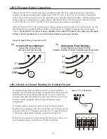
21. Input Control Signal Wiring. . . . . . . . . . . . . . . . . . . . . . . . . . . . . . . . . . . 47
22a. Universal Modules with Non-isolated Output. . . . . . . . . . . . . . . . . . . . . . 48
22b. Split-phase Modules with Non-isolated Output . . . . . . . . . . . . . . . . . . . . 48
22c. Universal Modules With 2-wire Plus Ground Isolated Output . . . . . . . . . 48
22d. Universal Modules With 3-wire Plus Ground Isolated Output . . . . . . . . . 48
22e. Universal Modules With 2-wire Plus Ground Isolated Output . . . . . . . . . 49
23. Installation Wiring Diagram for Axxium Pro Systems with External
Bypass Switch (L1, N), Isolated Output, and Universal Power Modules. . 50
24. Installation Wiring Diagram for Axxium Pro Systems with External
Bypass Switch (L1, L2), Isolated Output, and Universal Power Modules . 50
25. Installation Wiring Diagram for Axxium Pro Systems with External Bypass
Switch (L1, L2, N), Isolated Output, and Universal Power Modules . . . . 51
26. Installation Wiring Diagram for Axxium Pro Systems with External Bypass
Switch (L1, N), Non-isolated Output, and Universal Power Modules . . . . 52
27. Installation Wiring Diagram for Axxium Pro Systems with External Bypass
Switch (L1, L2), Non-isolated Output, and Universal Power Modules . . . 52
28. Installation Wiring Diagram for Axxium Pro Systems with External Bypass
Switch (L1, L2, N), Non-isolated Output, and Split-phase Power Modules53
29. Installation Wiring Diagram for Axxium Pro Systems with No External
Bypass (L1, N), Isolated Output, and Universal Power Modules . . . . . . . 54
30. Installation Wiring Diagram for Axxium Pro Systems with No External
Bypass (L1, L2), Isolated Output, and Universal Power Modules. . . . . . . 54
31. Installation Wiring Diagram for Axxium Pro Systems with No External
Bypass (L1, L2, N), Isolated Output, and Universal Power Modules . . . . 55
32. Installation Wiring Diagram for Axxium Pro Systems with No External
Bypass (L1, N), Non-isolated Output, and Universal Power Modules. . . . 56
33. Installation Wiring Diagram for Axxium Pro Systems with No External
Bypass (L1, L2), Non-isolated Output, and Universal Power Modules . . . 56
34. Installation Wiring Diagram for Axxium Pro Systems with No External
Bypass (L1, L2, N), Non-isolated Output, and Universal Power Modules 57
35. Balancing Recptacle Loads . . . . . . . . . . . . . . . . . . . . . . . . . . . . . . . . . . . 58
36. Breakaway Panel Links . . . . . . . . . . . . . . . . . . . . . . . . . . . . . . . . . . . . . . 59
37. Bus-bar Extension Installation . . . . . . . . . . . . . . . . . . . . . . . . . . . . . . . . . 59
38. Battery Cable Assembly Installation . . . . . . . . . . . . . . . . . . . . . . . . . . . . 60
Tables
8. UPS Dimensions . . . . . . . . . . . . . . . . . . . . . . . . . . . . . . . . . . . . . . . . . . . 33
9. Bypass Switch Positions . . . . . . . . . . . . . . . . . . . . . . . . . . . . . . . . . . . . . 38
10. Bypass Switch Specifications. . . . . . . . . . . . . . . . . . . . . . . . . . . . . . . . . . 39
11. Required Input Circuit Breaker Sizes (200–240 VAC, 50/60 Hz) . . . . . . . 41
12. United States Recommended AWG and mm
Wire Sizes . . . . . . . . . . . . . 42
13. Choosing an Installation Wiring Diagram . . . . . . . . . . . . . . . . . . . . . . . . 44

