34
1103 Rack Mounting Guidelines
The 3-slot and 6-slot UPS cabinets may be installed in an EIA-standard
19-in. (483-mm) equipment rack. An optional rack mounting kit,
containing brackets and required hardware, is available for such an
installation. For each 3-slot bay, use the following mounting procedure
to convert the UPS cabinet and install it in the equipment rack:
NOTE: The UPS chassis is heavy. This procedure requires two
people to lift and position the chassis into the equipment
rack. Install the cabinet in the rack before installing power
modules and battery modules, and before plugging the UPS
into the intended power outlet.
1. Remove the four screws (two on either side) securing the top cover
of the UPS. Carefully lift the cover straight up and off, to avoid
stressing the operator control panel. Set the cover aside.
2. Remove each of the two cabinet side panels (4 panels in 6-slot
cabinets) by lifting the top edge. No other hardware must be detached.
Store or discard the side panels.
3. Carefully replace the UPS top cover and secure with the four screws
removed in Step 1.
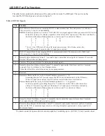
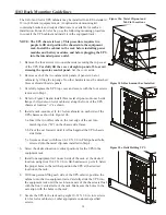
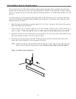
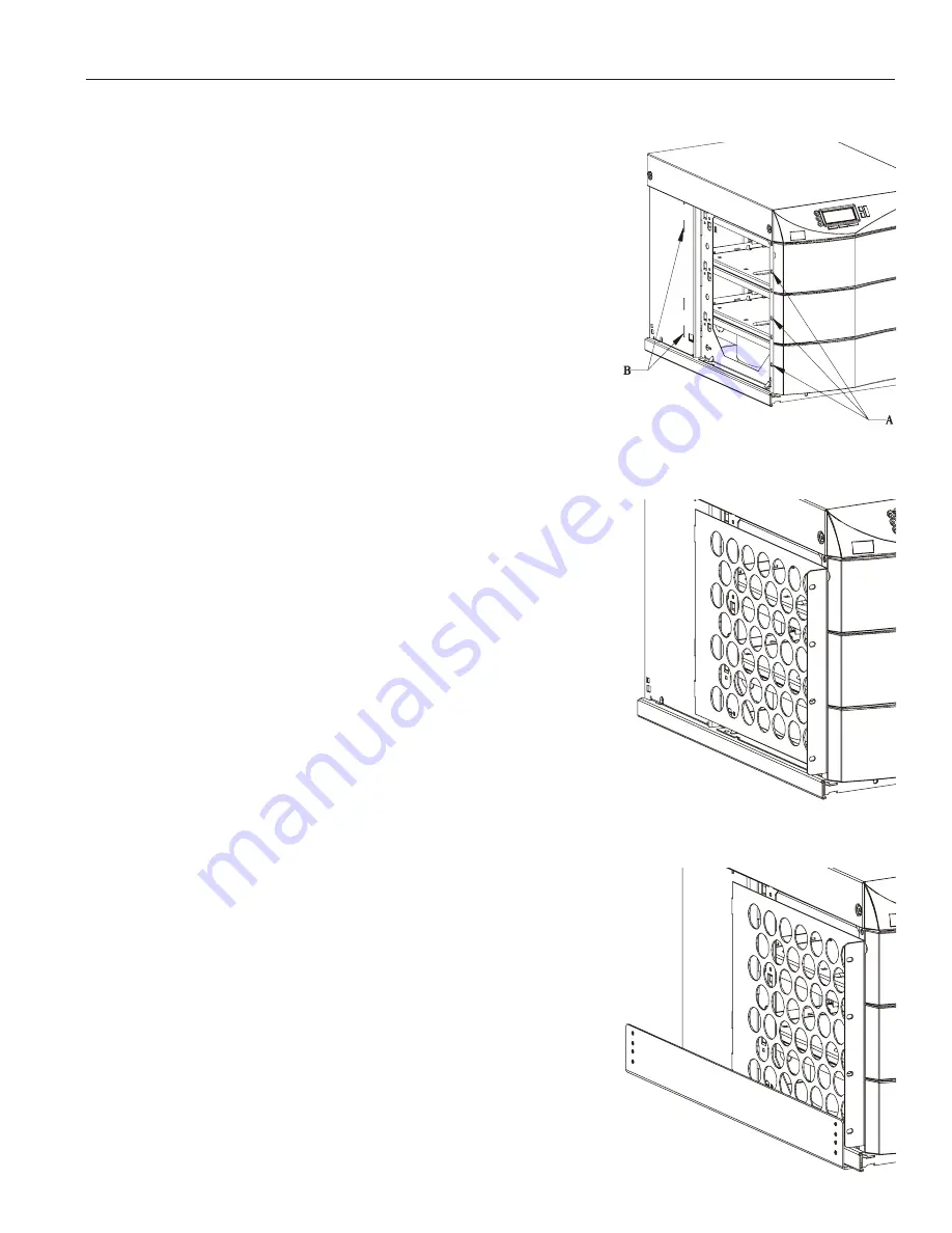
4. Refer to Figure 10a and install three metal clip-nuts onto each side
flange (6 clip-nuts on 6-slot cabinets) along the front of the UPS
chassis at location “A” as shown.
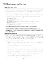
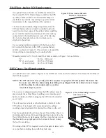
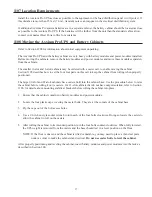
5. Install a rack-mount ear (2 for 6-slot cabinets) on each side of the
UPS chassis as shown in Figure 10b.
5.a. Insert the two offset tabs on the rear edge of the ear into
matching slots (“B”) on the chassis side frame.
5.b. Pivot the ear forward, until it is flush against the UPS chassis
side frame.
5.c. Secure each ear with three 1/4-20 X 1/2-in. Philips-head bolts,
screwed into the metal clip-nuts installed in Step 4.
6. Select the desired location (vertical position) for the UPS in the
equipment rack.
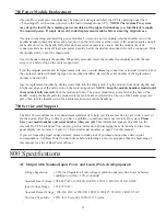
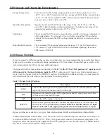
7. Install one equipment rail on each side of the rack, at the desired
location, using four 10-32 X 1/2-in. flat-head screws per rail. Select
the proper holes in the rail that position the UPS at the desired
location in the rack.
8. With one person lifting each side of the UPS cabinet, position the
cabinet onto the two equipment rails. Carefully slide the UPS into
the equipment rack until the rack-mount ears of the chassis are flush
with the front vertical rails of the rack. Make sure the holes in the
ears align with the holes in the rack.
9. Secure the UPS in the rack using eight 10-32 X 1/2-in. torx screws
(16 for 6-slot cabinets) or other appropriate customer-specified
screws.
Figure 10a. Metal Clip-nut and
Tab Slot Locations
Figure 10b. Rack-mount Ear Installed
Figure 10c. Rails Holding UPS

