42
1302 Installing External Bypass Switches
For hardwired UPS installations, the bypass switch must be incorporated in the fixed wiring and be readily
accessible.
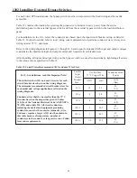
Table 12 contains information for selecting the proper size conductor to carry power from the service
distribution panel to the external bypass switch, and from the external bypass switch to the load distribution
panel.
For installations in the U.S., select the conductor size based upon the input circuit breaker rating, as listed in
Table 12. In other locations, refer to local wiring code requirements to determine conductor sizes. Always use
wiring rated at 75 ºC, minimum.
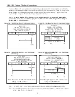
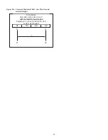
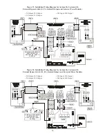
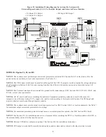
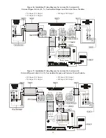
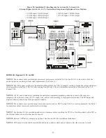
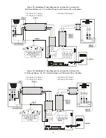
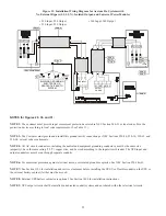
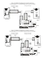
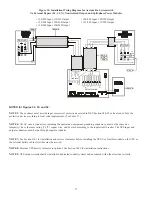
Refer to the wiring diagrams in Figures 23 through 34, based upon the intended UPS input and output voltages,
to determine the maximum input and output current and required circuit breaker sizes.
After installing all input and output wiring on the bypass switch, secure all connections by tightening all screws
to the torque values specified in Table 12.
Table 12. United States Recommended AWG and mm
2
Wire Sizes
For U.S. installations, read this Important Note!
This table lists the AWG and mm
2
wire size for each
circuit breaker size shown on the wiring diagrams.
The minimum recommended circuit breaker sizes for
each model and voltage application are listed on the
wiring diagrams.
Conductor sizes shall be no smaller than the 75º C
wire size based on the ampacities given in Tables
310-316 of the National Electrical Code, ANSI/NFPA
70-1993, and article 220. All circuit conductors,
including the neutral and equipment grounding
conductors, must be the same size (ampacity) wire.
Code may require a larger AWG size than shown in
this table because of temperature, number of
conductors in the conduit, or long service runs. Follow
local code requirements.
For this
Input
Circuit
Breaker
Size...
Use this Size
75º C Copper Wire
Conductor Screw
Torque
AWG
mm
2
in-lb
(Nm)
25 A
10
5.3
20
(2.3)
50 A
8
8.4
25
(2.8)
100 A
70 A
3
4
26.7
21.2
45
(5.1)
35
(4.0)
125 A
1
55
(6.2)
150 A
1/0
53.5
42.1
65
(7.3)

