60
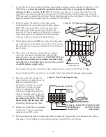
tabs between the stud block and the fuse end and
between the other stud block and the cable
terminal.
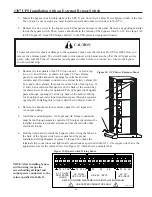
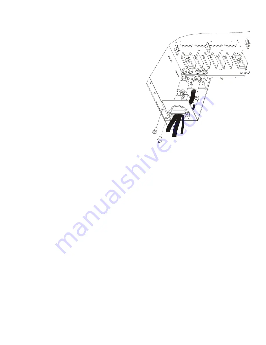
11. Align the screw holes of the cable assembly’s entry
plate with holes on the cabinet side panel as shown
in Figure 38. Secure the entry plate with screws
supplied with the cable assembly.
12. Secure the cable assembly terminals by tightening
the nuts onto the back plane bus bars. Also tighten
the third nut, holding the other fuse end. Torque all
three nuts to 75–85 in-lb (8.5–9.6 Nm).
12. Replace the cabinet back panel, and secure it with
its screws.
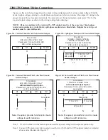
12. Install the other end of the external battery cabinet
cable assembly on the rear of the battery cabinet by
following the above steps. Use the back panel of
the top bay to locate the entry plate of the cable
assembly. (The bus-bar extension assembly is
already installed in the battery cabinet.)
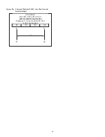
15. If an additional battery cabinet will be connected to the first, in a series connected (daisy-chain)
configuration, use another external battery cabinet cable assembly for the connections between the battery
cabinets. Locate the daisy-chained cable on the rear of the first battery cabinet in the bay below the location
of the first cable assembly. Follow this procedure for connecting any additional daisy-chained battery
cabinets.
16. After making and verifying all battery cabinet cable connections, install all battery modules in all UPS and
external battery cabinets.
17. Ensure that all power modules are properly installed and latched into the UPS cabinet.
18. Apply input power to the UPS by closing the service circuit breaker or turning the external bypass switch to
the line position.
19. Observe the output voltage on the UPS display (menu 3 10 ) and make sure that the total battery
capacity (parameter 0205) is correct.
20. Place the UPS into operation by turning the external bypass switch to the UPS position.
Figure 38. Battery Cable Assembly Installation

