9
Off mode turns off the output and most internal circuitry. Within this mode, another mode (Sleep) turns off all
internal circuitry when AC line is not present and battery voltage drops to a low threshold. If the Battery
Protect (BP) function is selected and input AC voltage is not present, the UPS goes into Sleep mode
immediately when the UPS is turned off. When input AC voltage returns, the UPS automatically recovers from
Sleep mode and, if the Autorestart parameter is enabled, switches to Double Conversion. Autorestart is enabled
as a factory default.
Figure 3 shows the basic functional elements of the UPS.
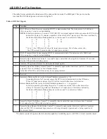
203 Operator Control Panel
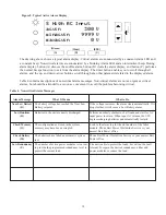
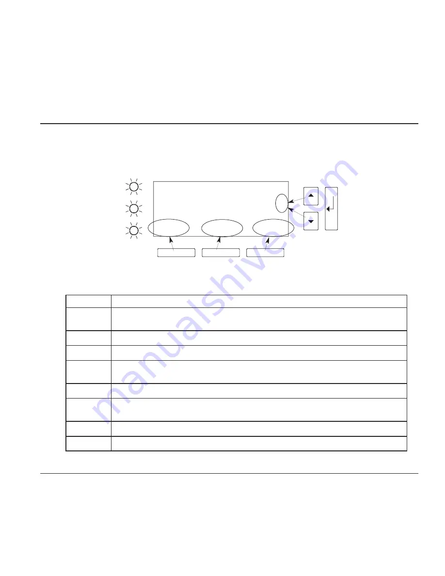
The operator control panel has an alphanumeric display, three LED indicators, and six pushbuttons as described
in Figure 4 and in Table 1.
204 Power Connections
See Part II Section 1300 of this manual for details about connecting power to the UPS and how to connect load
equipment to the UPS.
For information about installing or replacing batteries, refer to Section 700, Maintenance and Service.
For information about connecting/disconnecting external battery cabinets, refer to Section 1400.
(1)
(2)
(3)
(4)
(A)
(B)
(C)
4 24
USER
#3
Wout
`
watts
2.37 KW
Slot
Top
ESC
Item
Description
1
Alphanumeric display of unit function and operating parameters. Also displays
alarm/data logs.
2
Alarm LED (red). Lights to signal that the unit has detected an alarm condition.
3
Battery LED (yellow). Lights to signal that the unit is operating on battery power.
4
Line LED (green). Lights to signal that the unit is operating on AC line power and
producing output voltage.
A and B
Multi-function buttons, as labeled by the bottom line of the alphanumeric display.
C
Menu/Escape button, for moving into and out of display menus. Also, for avoiding a
change to a parameter value.
s
and
t
Menu scroll up and down buttons. Also, for increasing/decreasing parameter value digits.
¿
Enter button, to activate/accept displayed parameter or operating mode.
Figure 4. Operator Control Panel
Table 1. Control Panel Details


