background image

13

ENGLISH

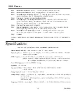
DB-9 Pinouts

Pin 1

RS232 Receive Data: Receives incoming RS232 communication data.

Pin 2

RS232 Transmit Data: Sends outgoing RS232 communication data.

Pin 3

Normally Open On-Battery Contact: A normally open contact that closes 15 seconds
(pulls to Common) after the UPS switches to battery power.

Pin 4

Common: The signal ground for all signal pins.

Pin 5

Normally Open Low-Battery-Alarm Contact: A normally open contact that closes
(pulls to Common) during a Low Battery Alarm. This tells CheckUPS II and other 
shutdown software when to start a computer shutdown.

Pin 6

Plug and Play Sense for Windows 95.

Pin 7

Remote Shutdown: Connecting this pin to Common for at least 5 seconds, while the
UPS is operating on battery, shuts the UPS off after 120 seconds.

Pin 8

Normally Closed On-Battery Contact: A normally closed contact that opens 
15 seconds (releases from Common) after the UPS switches to battery power.

Pin 9

Unused.

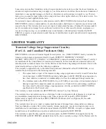
Contacts consist of open collector circuits capable of switching up to +30 VDC, 6 mA resistive
load.

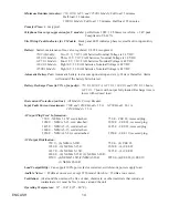
Specifications

B

est Power reserves the right to change specifications without prior notice.

Line Transient Protection: Passes ANSI/IEEE C62.41 Category A testing.

Safety Compliance: Model U: Tested to UL1449; listed to UL1778, and CAN/CSA C22.2 No. 107.1 M91.

Model E: TÜV/GS listed.

EMC Compliance: Model U: FCC Class A; except 750 VA model complies to FCC Class B.

Model E: CISPR 22 Class B, Vfg 243-91/46-92 B, EN55022, CE Mark Self-certified

to: CE Marking Directive 93/68/EEC, Low Voltage Directive 73/23/EEC

Noise (RF) Suppression: Full-time EMI/RFI filtering.

Efficiency: > 95% on line.

Capacity VA/Watts: 750VA / 450W; 1050VA / 670W; 1425VA / 950W; 1800VA / 1260W; 

2250VA / 1600W.

Voltage Nominal:  Model U: 120 VAC, Model E: 230 VAC

Voltage Range:  Model U:  0 to 160 VAC operating on battery and buck/boost; 96 to 146 VAC operating on

buck/boost only.
Model E:  0 to 300 VAC operating on battery and buck/boost; 188 to 270 VAC operating
on buck/boost only.

Frequency: 50/60 Hz auto-sensing 55 - 65 Hz (60 Hz); 45 - 55 Hz (50 Hz) (50/60 Hz ± 0.5 Hz on battery.)

Summary of Contents for Fortress 1050 VA

Page 1: ...USER GUIDE Fortress Rackmount 750 VA 1050 VA 1425 VA 1800 VA and 2250 VA...

Page 2: ...ge must be limited to 3 mA on the U model and 2 5 mA on the E model If you do not know the load leakage current replace the UPS power cord with a power cord that uses a lock ing plug with a minimum ra...

Page 3: ...F o r t r e s s Rackmount 750 VA 1050 VA 1425 VA 1800 VA and 2250 VA User Guide FSS 0388B Copyright 1998 Best Power All rights reserved...

Page 4: ...he unit If you prefer you can contact Best on the World Wide Web to get more product information Best s toll free Fax on Demand service is also available 24 hours a day to give you access to technical...

Page 5: ...eplacing the Batteries 10 Battery Replacement Instructions 11 Communication Port 12 DB 9 Pinouts 13 Specifications 13 Warranty 15 Appendix A Adjusting Voltage Settings 17 Best Power Offices 20 Tradema...

Page 6: ...bove 25 Celsius 77 Fahrenheit recharge the batteries more often CAUTION Whenever the Fortress is On there may be dangerous voltage present at the unit s outlets This is true because the unit s battery...

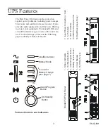
Page 7: ...panel LEDs and an audible alarm keep you aware of the unit s sta tus Use the drawings on this and the following page to identify features of the unit Line Buck boost Battery Mode Load or Battery Char...

Page 8: ...ULT 1050 1425 E 1050 1425 U 1 Status Indicators 8 5 15 Outlets 1800 and 2250 2 On Standby Button have breaker 3 Alarm Program Button 9 5 20 Outlets 2250 has breaker 4 Battery Access Panel 10 L5 30 Out...

Page 9: ...hardware from electronics distributors below the intended rack location for the Fortress Secure the shelf or brackets at both the front and back of the rack using bolts nuts and washers Carefully lift...

Page 10: ...main on If the unit beeps or if the top light does not remain on even though input power is available from the wall outlet go to the Troubleshooting section 4 Switch off the equipment you want to prot...

Page 11: ...s labled Site Wiring Fault lights to indicate a wiring fault in the circuit to which the Fortress is connected If this LED is on the outlet needs to be checked and repaired by an electrician Do not us...

Page 12: ...is running on battery power Output Overload Refer to Tables 2 and 3 Replace the Battery or UPS Fault Refer to Tables 2 and 3 Blinking The unit is boosting or bucking utility power Boost Automatically...

Page 13: ...onds 1 Utility power outage 2 Loose plug 3 Tripped circuit breaker 4 Power cord failure 1 Wait for power to return 2 Make sure the power cord is connected 3 Reset the circuit breaker 4 Phone Best Powe...

Page 14: ...s could fall into the UPS Never allow any tool to contact both a battery terminal and the UPS cabinet or another battery terminal Do not lay tools or metal parts on top of batteries To ensure continue...

Page 15: ...plug the protected load equipment from the Fortress Then turn off the Fortress and disconnect the line cord 3 Use the drawings below to identify the location on the battey pack in the model Fortress t...

Page 16: ...l to the front panel 11 If you followed the option in step 2 Reconnect the line cord to the Fortress and turn the unit on 12 Reconnect the load equipment Switch on the protected load equipment one pie...

Page 17: ...n 9 Unused Contacts consist of open collector circuits capable of switching up to 30 VDC 6 mA resistive load Specifications Best Power reserves the right to change specifications without prior notice...

Page 18: ...me to 95 of capacity 750 VA 1050 VA 1425 VA 1800 VA and 2250 VA 3 hours 1425 VA 7 hours with output fully loaded Recharge time is lower with reduced load Overcurrent Protection on line All Models Circ...

Page 19: ...he PURCHASER must promptly notify BEST POWER in writing within the duration of the warranty or not later than one month after expiration of the warranty BEST POWER s obligation under this warranty is...

Page 20: ...the Product beginning with the date of sale to the initial retail purchaser subject to the following conditions This warranty is applicable only to the initial retail purchaser hereinafter called PURC...

Page 21: ...above limitation on duration of implied warranties may not apply to you Some states do not allow the exclusion or limitation of incidental or consequential damages so the above limitation or exclusio...

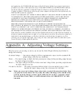
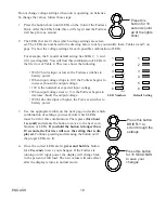
Page 22: ...en input voltage rises to 130 the Fortress begins to decrease buck the output voltage With 146 volts input or higher the Fortress switches to battery power 3 Use the appropriate table on the next page...

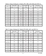
Page 23: ...146 156 1 2 5 90 104 128 146 156 Table 4 Voltage Settings for U Models 750 1050 1425 1800 and 2250 VA Table 5 Voltage Settings for E Models 750 1050 1425 and 2250 VA 270 244 230 200 180 3 4 6 284 250...

Page 24: ...NGAPORE 188647 Telephone 65 430 6168 FAX 65 430 6170 Sola Australia Ltd 13 Healey Road Dandenong Victoria 3175 AUSTRALIA Telephone 61 3 9706 5022 FAX 61 3 9794 9150 BEST House Wykeham Industrial Estat...

Page 25: ...is equipment has been tested and found to comply with the limits for a Class A digital device pursuant to Part 15 of FCC Rules These limits are designed to provide reasonable protection against harmfu...

Page 26: ...FSS 0388A...

Reviews: