background image

3

Nest Easel

Assembly Diagram

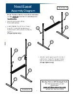
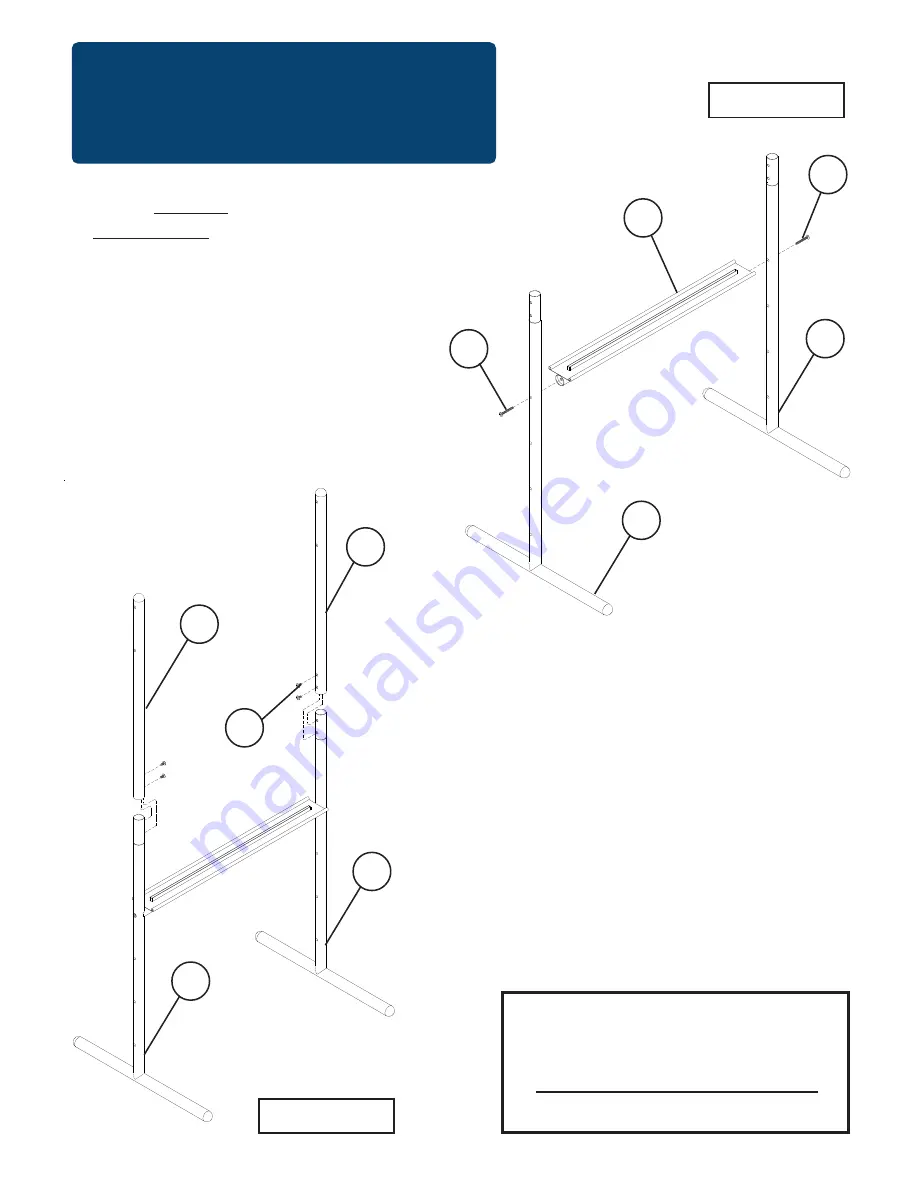
Illustration # 1

To Assemble:

Identify and Separate all the
Parts and Hardware.

Attach Middle Tray (P-3) to 2 Lower
Legs (P-1) at desired height using 2
Socket Screws (B) as shown in illustra-
tion # 1.

(Finger tighten only)

Illustration # 2

R

EAD

 T

HROUGH

 I

NSTRUCTIONS


FROM


BEGINNING

TO


END


BEFORE


STARTING


TO


ASSEMBLE


UNIT

.

Attach 2 each Upper Legs (P-2) to the 2
each Lower  Legs (P-1) using 4 Socket
Screws (A) as shown in illustration # 2.

(Finger tighten only)

Missing Parts or UPS Damaged Parts

For Your Convenience you can

EMAIL us at

support@moorecoinc.com

24HOURS 7 DAYS A WEEK

1.

2.

Illustration # 2

B

P-1

P-3

P-1

A

P-2

B

P-2

P-1

P-1

3.

Summary of Contents for Nest Easel

Page 1: ...345678901234567890121234567890123456789012345678901212345678901234 123456789012345678901234567890121234567890123456789012345678901212345678901234 123456789012345678901234567890121234567890123456789012345678901212345678901234 123456789012345678901234567890121234567890123456789012345678901212345678901234 123456789012345678901234567890121234567890123456789012345678901212345678901234 12345678901234567...

Page 2: ...Caster for Back 2 EA F Plastic Chart Support 4 EA G Allen Wrench 1 EA H Caster Wrench 1 EA Hardware List Should you require assistance during assembly please call our Customer Service Department Monday Friday 8 a m 5 p m Central Standard Time Toll Free Customer Service 1 800 749 2258 P 1 Lower Leg 2 EA P 2 Upper Leg 2 EA P 3 MiddleTray 1 EA P 4 Top Support 1 EA P 5 Markerboard 1 EA P 6 Bookrack Ba...

Page 3: ...Finger tighten only Illustration 2 READ THROUGH INSTRUCTIONS FROM BEGINNING TO END BEFORE STARTING TO ASSEMBLE UNIT Attach 2 each Upper Legs P 2 to the 2 each Lower Legs P 1 using 4 Socket Screws A as shown in illustration 2 Finger tighten only Missing Parts or UPS Damaged Parts For Your Convenience you can EMAIL us at support moorecoinc com 24HOURS 7 DAYS A WEEK 1 2 Illustration 2 B P 1 P 3 P 1 A...

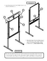
Page 4: ...the product until repairs are made by your dealer using factory authorized parts Insert Markerboard P 5 into Middle Tray P 3 as shown in illustration 3 4 5 Illustration 3 Illustration 4 Slide Top Support P 4 over Markerboard P 5 and secure to the 2 Upper Legs P 2 using 2 each Socket Screws B as shown in illustration 4 Finger tighten only P 2 P 5 P 3 P 2 P 4 B B P 5 ...

Page 5: ...G Tighten all Screws at this time Illustration 5 Attach 2 Plastic Chart Supports on each side of board Insert 2 pins on back side of Chart Support F through holes in markerboard P 5 as shown in illustration 6 B Press Plastic Chart Support F firmly to the Markerboard surface Illustration 6 A Illustration 6 B Peel the paper from the back of adhesive pad on Plastic Chart Support F See Illustration 6 ...

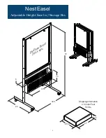
Page 6: ...6 Nest Easel Adjustable Height Easel w Storage Bin Shipping Information 4 0 Cubic Feet 56 lbs 41 25 6 72 34 24 Dry Erase Board 28 x 40 10 31 6 ...

Page 7: ...7 ...

Reviews: