30
Step (B):
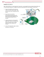
Install the Processor
1.
Hold the processor with your thumb and
index finger as shown to align your fingers
with the socket cutouts.
2.
Make sure that the processor Pin#1
indicator (gold triangle) is aligned with the
Pin#1 chamfer on the socket.
3.
Make sure that the notches on the
processor align with the posts on the
socket.
4.
Lower the processor straight down without
tilting or sliding it in the socket.
Step (C):
Close the Load Plate
1.
Carefully lower the “Load Plate” and make sure it
slides under the shoulder screw cap as the lever is
lowered.
2.
Continue to low the lever.
3.
Latch the socket lever under the load plate tab.
Summary of Contents for BNX-H110
Page 1: ...1 Security Board BNX H110 Always at the forefront of innovation User Manual...
Page 6: ...6 Chapter 5 Programming Guide 5 1 Bypass Setting 46 5 2 GPIO 50...
Page 7: ...7 Chapter 1 General Information...
Page 11: ...11 Figure 1 1 Board Layout of BNX H110 1 4 Board Layout...
Page 12: ...12 Chapter 2 Preparation...
Page 16: ...16 2 5 Locations Of Jumpers and Connectors...
Page 25: ...25 Factory Default Power Reset Switch SW1 Up Power Switch Reset Switch Down Factory Default...
Page 26: ...26 Chapter 3 Operation...
Page 34: ...34 Chapter 4 BIOS Setup...
Page 40: ...40 CPU Configuration Display CPU Information 4 6 The Chipset Menu...
Page 45: ...45 Chapter 5 Programming Guide...


