32
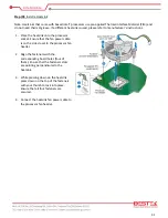
BNX-H110 motherboard requires correct power plan to properly support Intel® LGA1151 Gen-6 Core-i
Processor. Please add the 24-pin ATX Power Connector on the blue connector, and 4-pin 12Vdc Power
Connector on the red connector.
In case the 12Vdc Power Connector is not added, power supply will be triggered, but the motherboard would
not boot at all. Please shutdown the system, and add the 12Vdc Power Connector back on.
3.4 Adding Power Connectors
Summary of Contents for BNX-H110
Page 1: ...1 Security Board BNX H110 Always at the forefront of innovation User Manual...
Page 6: ...6 Chapter 5 Programming Guide 5 1 Bypass Setting 46 5 2 GPIO 50...
Page 7: ...7 Chapter 1 General Information...
Page 11: ...11 Figure 1 1 Board Layout of BNX H110 1 4 Board Layout...
Page 12: ...12 Chapter 2 Preparation...
Page 16: ...16 2 5 Locations Of Jumpers and Connectors...
Page 25: ...25 Factory Default Power Reset Switch SW1 Up Power Switch Reset Switch Down Factory Default...
Page 26: ...26 Chapter 3 Operation...
Page 34: ...34 Chapter 4 BIOS Setup...
Page 40: ...40 CPU Configuration Display CPU Information 4 6 The Chipset Menu...
Page 45: ...45 Chapter 5 Programming Guide...


