background image

1

1

2

22

ENGI

N

E DIS

A

S

SEM

BL

Y

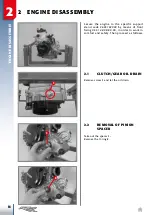
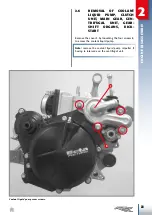
2.5.1  Removal of start motor

Remove the two screws

 1

and extract the motor.

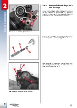
2.5.2  Bendix coupling removal

Extract the Bendix coupling 

1

 once the complete 

flywheel cover and flywheel have been removed 

(see par. 2.4).

Summary of Contents for RR 125 2T MY 2018

Page 1: ...125 2T 200 2T WORKSHOP MANUAL 035 44 009 00 00 ...

Page 2: ...NT LIQUID PUMP AND CENTRIFUGAL UNIT 86 3 9 1 CHECK OF PUMP UNIT AND DISASSEMBLY CENTRIFUGAL UNIT AND IDLER UNIT 87 3 9 2 CENTRIFUGAL UNIT ASSEMBLY 88 3 9 3 PUMP UNIT ASSEMBLY 91 3 9 4 ASSEMBLY OF COMPLETE CLUTCH COVER AND PUMP UNIT 91 3 10 OUTER CLUTCH COVER COUPLING 93 3 11 ELECTRIC IGNITION UNIT ONLY RR200 94 3 11 1 BENDIX COUPLING CHECKS 94 3 11 2 IGNITION UNIT COUPLING TO ENGINE 94 3 12 IGNITI...

Page 3: ...CHECK OF THE CRANKCASE CYLINDER GASKET THICKNESS 110 3 13 8 HEAD APPLICATION 111 3 13 9 EXHAUST VALVE ADJUSTMENT 112 3 14 CHECK ON INTAKE UNIT AND ASSEMBLY 116 3 15 INSERTION OF PINION SPACER AND APPLICATION OF THE OIL EXHAUST CAP 119 4 ENGINE REASSEMBLY IN THE VEHICLE 120 TABLE OF ENGINE COMPONENTS TIGHTENING TORQUES 130 TABLE OF FRAME ENGINE FASTENING TORQUES 133 TABLE OF SUPERSTRUCTURE FASTENIN...

Page 4: ... refer to the spare parts manual for the specific vehicle or version The warranty and liability on vehicle safety lapses when maintenance or repair Are NOT performed by workshops specialised in repair of motorbikes and motorcycles Are NOT carried out carefully by following the requirements contained in the technical documentation Are NOT carried out by using special Betamotor tools where required ...

Page 5: ...cause burns The coolant contains dangerous substances that are harmful for the environment In order to change it one must be equipped for disposal in compliance with applicable laws Do not disperse coolant into the environment Keep out of the reach of children Hot parts The engine and the exhaust system get very hot and remain at that temperature for a long time even after the engine has been turn...

Page 6: ...5 Racing RR200 Bore mm Stroke mm 54 x 54 5 62 x 63 Displacement cm 124 8 190 Compression ratio 15 1 13 6 1 TRANSMISSION RR125 RR125 Racing RR200 Primary 23 73 1st gear ratio 12 33 2nd gear ratio 15 31 3rd gear ratio 17 28 4th gear ratio 19 26 5th gear ratio 21 25 6th gear ratio 20 20 ENGINE ...

Page 7: ...0 4 Crankcase Cylinder gasket check plate RR200 code 035 14 009 00 00 5 Flywheel blocking tool code 026 14 005 50 00 6 Flywheel extractor code 36 25173 000 7 Special wrench code 026 44 029 00 00 8 Special wrench code 007 44 035 00 00 9 Engine universal tool code 36 25132 000 10 Engine support code 035 14 008 80 00 Symbols 6Nm Silicone paste Value Tightening torque Threadlocker medium resistance Gr...

Page 8: ...and Disconnect the tank ventilation pipe Set the fuel valve to OFF and disconnect the fuel pipe from the valve Remove the seat Remove the two screws 1 fastening the tank to the frame and the screw 2 one per side fastening the side panel to the radiator Remove the tank along with the sides 1 2 1 1 ENGINE REMOVAL FROM VEHICLE ...

Page 9: ...each side and the pinion guard 4 Remove the circlip 5 and extract the pinion Rest the chain against the upper wedge 6 5 6 3 4 Remove the screws 7 and the side panel8 This allows easy access to the silencer screw 9 7 8 9 Remove the exhaust expansion and the si lencer ...

Page 10: ...ngine electrical system connec tors from the central system Cut all straps binding the engine s electric system to the vehicle Disconnect the engine ventilation pipes 10 Drain the cooling system through screw 10 and let the liquid outflow into a container the cooling circuit contains 1 3l of liquid Remove the radiator cap ...

Page 11: ...00 Remove the start motor cable fixing nut Pull the clutch lever and hold it in position for example by using a plastic clamp Pull the clutch lever and hold it in position for example by using a plastic clamp Remove the threaded fitting 11 11 ...

Page 12: ... operation WARNING Do not bring the liquid in contact with skin eyes or clothing In case of contact with eyes rinse them immediately with water and week medical advice with skin clean the concerned are as immediately with soap and water Change the clothing that came into contact with the liquid Remove the head connections Release and remove the brake pedal return spring 12 Remove the kickstarter l...

Page 13: ... the carburettor straps from the air fil ter sleeve and from the manifold 14 14 13 ONLY RR 200 Pull out the mixer tube 13 from the intake manifold and tube hold 14 WARNING When the mixer tube has been disconnected plug it to prevent emptying ...

Page 14: ...e lower fixing screws 15 one on each side and loosen the upper screws 16 one on each side Rotate the entire filter box unit 15 16 Remove the straps binding the electrical wir ing to the frame Remove the carburettor leaving it connected to the gas cable ...

Page 15: ...LE Remove the swingarm pin 17 and the upper shock absorber pin 18 Remove the engine pins 19 Extract the engine from the frame and apply it to the specific stand code 36 25132 000 using the specific front fixing bracket code 035 14 008 80 00 ...

Page 16: ... 3625132000 by means of front fixing 035 14 008 80 00 in order to work in comfort and safety Then proceed as follows 2 1 CLUTCH GEAR OIL DRAIN Remove screw 1 and let the oil drain 1 2 2 REMOVAL OF PINION SPACER Take out the spacer 1 Remove the O ring 2 2 1 2 ENGINE DISASSEMBLY ...

Page 17: ...MOVAL OF PISTON CYL INDER AND HEAD Remove the spark plug 1 and the spigot screws 2 together with the copper washers Remove the head and the two O rings Remove the three screws 3 and cover 4 4 3 2 1 5 Release the lock 5 and remove it ...

Page 18: ...the gasket 7 It may be necessary to slightly force the rubber gasket 8 place a metal pin A between the lever and the gasket 8 and slightly force it outwards Removal of gasket 7 A 7 6 8 Remove the four collar nuts 9 Extract the cylinder and the base gaskets 9 ...

Page 19: ... solid residue from falling inside the base Using a suitable tool to insert the specific seat A remove the elastic ring 10 A Removal of piston circlip Disassembling the piston pin bolt 10 Remove the pin bolt using a universal extractor for pin bolts Remove the piston the pin bolt and the bearing from the connecting rod foot ...

Page 20: ...ate re moval Remove the plastic straps that join the stator and pick up wiring Remove the four screws 1 fastening the flywheel cover 2 to the left crankcase Remove the flywheel cover and the gasket placed between the crankcase and the cover Pay attention to the two centring pins 3 on the crankcase Fixing screws 1 of flywheel cover 2 The two designated references pins 3 for the flywheel cover 1 2 3...

Page 21: ...etween the nut and the flywheel A To remove the flywheel tighten the extractor B code 3625173 onto the threaded part on the flywheel Keep the extractor blocked with a spanner and tighten the screw on the extractor using a box spanner Release of flywheel using special tool B 2 4 2 Stator removal Remove the two screws 1 fixing the stator 2 to the flywheel cover 3 Extract the plate 4 and the cable gl...

Page 22: ...2 20 ENGINE DISASSEMBLY Pick up removal 2 4 4 Removal of pick up unit Remove pick up 1 by loosening the two fixing screws 2 1 2 ...

Page 23: ...OVAL OF ELECTRIC IG NITION ONLY RR200 The electric ignition is carried out by means of start motor 1 that meshes on the bendix coupling 4 The coupling gear axially shifts and meshes onto the ring gear which is one with the flywheel due to the start motor rotation The coupling gear retracts to its rest position once the motor action ends ...

Page 24: ...SASSEMBLY 2 5 1 Removal of start motor Remove the two screws 1and extract the motor 2 5 2 Bendix coupling removal Extract the Bendix coupling 1 once the complete flywheel cover and flywheel have been removed see par 2 4 ...

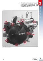
Page 25: ... UNIT MAIN GEAR CEN TRIFUGAL UNIT GEAR SHIFT ORGANS KICK START Remove the cover 1 by loosening the four screws 2 to access the coolant liquid pump Note remove the coolant liquid pump impeller if having to intervene on the centrifugal unit Coolant liquid pump cover screws ...

Page 26: ...3 4 2 24 ENGINE DISASSEMBLY Remove the outer clutch cover 3 by loosening the four screws 4 to access the clutch unit only Outer clutch cover screws ...

Page 27: ...complete overhaul of the engine or of gearshift organs kickstart primary transmission or centrifugal unit the inner clutch cover 5 must be removed by loosening the nine screws 6 after draining the gearbox oil Par 2 1 Inner clutch cover screws ...

Page 28: ...26 ENGINE DISASSEMBLY Pay attention to the two reference pins A placed between the right crankcase half and the inner clutch cover while disassembling Two centring pins A for inner clutch cover coupling A ...

Page 29: ...n fixing screw 1 once the coolant liquid pump cover has been removed Par 2 6 Cooling pump fixing screw 1 Removal of impeller Extract the impeller 2 and the thrust washer 3 2 3 Removal of pump body and gasket Extract the complete pump body 4 and remove gasket 5 5 4 ...

Page 30: ...ing the two screws 2 once the pump impeller has been removed par 2 6 1 Removal of centrifugal adjustment cover Remove the assembly consisting of adjusting springs 3 auxiliary springs 4 and spring guide 5 4 3 5 After removing the screw fixing the rocker arm 6 to the centrifugal control lever 7 extract the rocker arm with control rod and gasket 8 Disassembly of control rod rocker arm unit 7 8 6 ...

Page 31: ...INE DISASSEMBLY Removal of centrifugal control lever Extract the centrifugal control lever 7 together with the two thrust washers 9 7 9 Extract the complete centrifugal unit 10 Extraction of centrifugal unit 10 ...

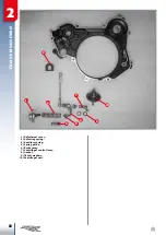
Page 32: ...2 30 ENGINE DISASSEMBLY 1 Adjustment cover 3 Adjusting spring 4 Auxiliary spring 5 Spring guide 6 Rocker arm 7 Centrifugal control lever 8 Gasket 9 Thrust washers 10 Centrifugal unit 4 5 7 6 9 10 3 1 8 ...

Page 33: ... coupling plate 1 together with the thrusting bearing 2 1 2 Block the entire clutch unit using the special tool A Cod 035 14 000 80 00 as shown in the figure and loosen the clutch locking nut A 3 Remove the clutch locking nut 3 Grasp the entire clutch unit and pull it towards you ...

Page 34: ...GINE DISASSEMBLY 5 4 Remove the roller cage 4 and the centre bearing 5 1 Clutch coupling plate 2 Thrusting bearing 3 Clutch locking nut 4 Roller bearing 5 Centre bearing 6 Schnorr washer 7 Washer 2 1 3 6 7 4 5 ...

Page 35: ... Clutch disassembly Block the clutch case using the soft jaws vice Progressively loosen the screws 1 until they are disengaged from their seat 2 Remove the spring plate 2 and the springs 3 3 4 Remove the clutch hub 4 and the washer 5 5 ...

Page 36: ...ate 6 together with the disc unit 7 After extracting these last parts the bare clutch case 8 remains The entire clutch unit is disassembled 6 1 Screws 2 Spring plate 3 Springs 4 Hub 5 Washer 6 Pressure plate 7 Clutch discs 8 Clutch case 2 1 3 6 7 5 4 8 ...

Page 37: ...2 35 ENGINE DISASSEMBLY Note if you want to check the wear of the case only you can disengage it from the clutch pack 9 by simply lifting the clutch pack 9 ...

Page 38: ...hly corrosive therefore be careful not to drop any of it on the painted parts of the vehi cle Protective gloves must be worn to perform this operation WARNING Do not bring the liquid in contact with skin eyes or clothing In case of contact with eyes rinse them immediately with water and week medical advice with skin clean the concerned are as immediately with soap and water Change the clothing tha...

Page 39: ...l After removing the entire clutch unit Par 2 6 3 apply the special tool A code 035 14 006 50 00 as shown in the figure Loosen the primary pinion nut by turning clockwise Remove the pinion 1 Removal can be facilitated by using a universal extractor 1 A ...

Page 40: ...ter shaft 1 moves the gear 2 This gear moves the idler wheel 3 which engages in its turn with the clutch case The device recoils thanks to the spring 4 The pedal kickstart Removal of circlip 5 thrust washer 6 and idler gear 3 Circlip 5 and thrust washer 6 3 4 2 1 5 6 Remove the circlip 5 the thrust washer 6 and the idler gear 3 3 6 5 ...

Page 41: ...d bring it to a rest position having it turn anti clockwise Releasing spring from crankcase Extraction of shaft from crankcase Complete pedal kickstarter shaft 9 2 1 4 10 11 4 A Turn the shaft anti clockwise and pull it off together with the sleeve 9 the spring 10 and the thrust washer 11 ...

Page 42: ...compressed and extract the shaft together with the specific washer 4 Gearshift with washer Disassembly of gear stop cam Disassembly of cam stop lever 4 1 3 1 2 2 5 8 9 7 A 6 In order to disassemble the stop cam 2 keep the cam stop lever moved 5 loosen the screw 6 and pull out the stop cam 2 In order to disassemble the stop lever loosen the screw 7 enough to allow the lever to move axially and go o...

Page 43: ...lve 3 Spacer 2 7 INTAKE SYSTEM The intake system mainly consists of the intake manifold 1 and reed valve 2 and the spacer 3 Disassemble by removing the four screws 4 fastening the intake manifold and the reed valve to the crankcases Fixing screws RR125 Fixing screws RR200 ...

Page 44: ...case screws Crankcase uncoupling stage Crankcase half reference pins 1 C B 3 A A Apply the special tool B Code 007 14 010 80 00 to the left crankcase half following the punching on the tool Fix the tool with the three M6x15 screws maximum torque 10Nm Tighten screw C on the special tool Slightly hit the gear secondary with a rubber mallet during said operation Once the crankcases have been detached...

Page 45: ...ive forks from the desmodromic de vice 4 3 4 2 1 2 2 8 3 Internal gearshift unit and complete gearbox The internal gearshift unit is made up of the desmodromic device 1 on which the fork 2 and two forks 3 are engaged The forks supported by the pins 4 drive the sliding wheels of the gearbox allowing the desired ratio to be engaged The desmodromic device is controlled by the stop cam located in the ...

Page 46: ...ay be required to remove the various components attached to them The bearings must be replaced if there is any play or jamming during rotation For removal heat the crankcase halves for 20 minutes at about 150 C Place the crankcase halves on a large surface where their whole seal surface can rest Remove the bearings by following the indications below Note it is recommended to mark the two forks tha...

Page 47: ... control bearing seal screw 3 the screws 4 and the relative primary bearing seal plates 5 from the inner side 2 9 1 Right crankcase half On the external side remove the kickstart ramp 1 and the oil seal 2 Bearing safety screw 3 Kickstart ramp 1 oil seal 2 ...

Page 48: ...n the figure are removed from the outside to the inside Where necessary removing the safety devices 3 and 4 seen above The centrifugal shaft bearing can be removed by using a universal extractor that must rest onto a purposely created metal plate ...

Page 49: ...e secondary shaft oil seal 2 the gearshift shaft oil seal 3 and the bush 4 from the external side Removal of outer side left crankcase half details Removal of left crankcase half bearings The bearings 5 6 7 and 8 are removed from the outside to the inside Remove cap 9 1 3 2 4 9 5 6 7 8 ...

Page 50: ...ankcase halves on a large surface where their whole seal surface can rest When the bearings cool down they drop into their seats on their own 3 1 CRANKCASE HALF The crankcase halves have some parts that require care and their integrity and condition must be checked The checks and assembly operations of the individual parts coupled to the crankcases are described below Clean the threading and oil p...

Page 51: ...Block the bearings 2 and 4 using the specific safety devices Apply the high resistance threadlocker threads and tighten the screws to the indicated torques 5 Apply the bearing 5 from the crankcase half external side until flush 1 2 3 4 6Nm 20Nm A The studs must be mounted after applying the medium strength threadlocker and tightened to the indicated torque WARNING The part of root A of the stud mu...

Page 52: ...screws 8 to the torque indicated prior depositing of medium resistance threadlocker Position of right crankcase half gearshift shaft bearing Apply the bearing 6 and insert it so that the outer surface is aligned with surface A Apply new oil seals to be pressed in seat until they are flush 6 A 7 8 10Nm ...

Page 53: ...tion of left crankcase half bearings Application of left crankcase half parts 9 6 Apply the new oil seals 6 7 and 8 from the crankcase half external side until flush Apply the bush with collar 9 ONLY RR200 3 1 2 4 5 7 20Nm Apply the studs prior depositing of medium strength threadlocker Tighten to the specified torque 8 WARNING The part of root A of the stud must be mounted in the crankcase half A...

Page 54: ...etween two tailstocks or similar instrument Verify the maximum measurement variation during a complete turn using comparators positioned on the coupling surfaces with the crankshaft bearings Allowed limit value 0 02mm Check the axial play between the connecting rod head and the half shafts Recommended play 0 4 0 7mm The distance between the two shoulders must be 57 0 05 If replacing the inserts ap...

Page 55: ...ase the crankshaft oil seal on the right crankcase half and couple the crankshaft to the left crankcase half Keep the conical part A on the crankshaft facing you In order to carry out this operation you must just push the shaft axially towards the crankcase Apply the two centring bushes 1 and 2 Insertion of the crankshaft in the right crankcase half A 1 2 ...

Page 56: ... detected axial play is greater before replac ing either the gearwheels or the forks check their state of wear Par 3 4 4 Use protective jaws to clamp the mainshaft and secondary shaft Remove the various elements and check that the support surfaces of the main shaft and sec ondary shaft show no abnormal wear or signs of seizure the sides of the teeth are free from chipping or abnormal wear the slid...

Page 57: ... the elements thoroughly and oil them with gear oil Always replace the circlips Clamp the mainshaft 1 using protective jaws as shown in the figure Apply the roller bearing 2 1 2 Apply gear 3 V gear washer 4 and circlip 5 3 4 5 Insert gear 6 III IV gear and circlip 7 taking care to place it in groove A 6 7 A ...

Page 58: ...3 56 ENGINE CHECKS AND ASSEMBLY 9 Apply the toothed washer 8 so that it engages in the broaching and the roller cage 9 8 11 Insert gears 10 VI gear and 11 II gear 10 12 Insert washer 12 ...

Page 59: ...W OF PRIMARY UNIT 2 Gear mainshaft 3 Roller cage 18x22x10 4 Thrust washer 17 25 1 5 Fifth gear on primary 6 Second gear on primary 7 Washer 22 28 1 8 Circlip SW 22 1 2 9 Washer 22 26 1 10 Third and fourth gear on primary 11 Sixth gear on primary ...

Page 60: ...reassembly clean all the parts thoroughly and oil them by using gear oil Always replace the circlips Clamp the secondary shaft using protective jaws as shown in the image Apply the roller cage 1 1 Insert gear 2 II gear washer 3 and circlip 4 2 3 Insert gear 5 VI gear and circlip 6 5 4 6 ...

Page 61: ...3 59 ENGINE CHECKS AND ASSEMBLY Insert washer 7 and the two roller cages 8 8 7 Insert gear 9 IV gear 9 Insert gear 10 washer 11 and circlip 12 10 11 12 ...

Page 62: ...3 60 ENGINE CHECKS AND ASSEMBLY Insert gear 13 V gear and washer 14 13 14 Insert roller cage 15 followed by gear 16 I gear and washer 17 15 16 17 ...

Page 63: ...cage 22x26x10 7 Second gear on secondary 8 Washer thickness 9 Circlip 24 SW 10 Sixth gear on secondary 11 Fourth gear on secondary 12 Third gear on secondary 13 Fifth gear on secondary 14 Washer thickness C72 20 30 1 15 Roller cage 20x24x10 16 First gear on secondary 17 Thrust washer 17x30x1 ...

Page 64: ...e up of two gearshift forks 19 which drive two gears on the secondary unit one gearshift fork 20 which drives one gear on the primary unit three drive pin bushes 18 two gearshift fork pins 17 desmodromic gearshift 9 through whose rotation the gearshift forks are driven thus selecting the desired gear Check to make sure that the drive pins which sup port the bushes 18 have no traces of meshing or a...

Page 65: ...eas of the forks and in the housing areas with the crankcases Fork pin outside diameter limit 13 75mm Roll the fork pin on a perfectly flat surface if deformations are present proceed with replace ment Slide the gearshift forks on the respective pins if the movement is difficult and jamming occurs replace both the fork and the pin Make sure that the desmodromic control device has no corroded or wo...

Page 66: ...uce the gearshift forks together with the drive bushes on the gear tracks To be precise the smaller fork 3 drives the sliding gear on the primary unit while the other two 4 drive the sliding gears on the secondary unit Note the two forks 4 are interchangeable and their positioning is univocal since the drive pin must face the desmodromic device Place the forks in their original positions if none o...

Page 67: ...crankcase half Position the two forks 5 of the secondary unit in the external guides of the desmodromic device 6 and just like the primary unit fork insert the fork pin first in the pins and then in its proper seat Remember to oil the shafts forks and the desmo dromic device with plenty of gear oil Apply some grease on the crankcase edge in the mating area with the gasket and place a new gas ket P...

Page 68: ...3 66 ENGINE CHECKS AND ASSEMBLY View inside the right crankcase with crankshaft gearbox shafts complete with wheels internal gearshift and gasket ...

Page 69: ...e area of the cylinder and reed valve seat At the end of the operation use a rubber mal let to position the crankshaft by striking both the right and left half shafts until the shaft rotates freely WARNING Take care not to burn the oil seal To avoid this protect it with paper or metal buffer with an outer diameter of 24mm Press the left crankcase half towards the right making sure that the shafts ...

Page 70: ...te make sure that the dis tance between the movable pawl and the drive shaft is between 0 35 0 60mm Should the distance be greater replace the mov able pawl Allowed distance between shaft and pawl 0 35 0 50 In order to replace the movable pawl 1 disassem ble the return spring of the gearshift 2 the spring guide 3 the spring 4 which must be compressed and pulled out of its seat and the pawl moving ...

Page 71: ...aft note the gearshift return spring position For reassembly couple the movable pawl 9 to the drive shaft 10 and while compressing it insert the spring 8 between the movable pawl and the drive shaft Then apply the spring guide 7 the gearshift return spring 6 and finally the thrust washer 5 14x30x1 The gearshift return spring must be positioned as in the figure to be able to carry out its function ...

Page 72: ...pply the spring 14 so that the hook fits into the groove on the lever 16 and then apply the washers 13 and the screw 11 M6x20 spreading with medium strength threadlocker on the thread Stopping device At the end of the assembly check that the lever can rotate freely If it is blocked repeat the as sembly as described above Apply the entire device on the crankcase half so that the straight segment of...

Page 73: ...ten to the indicated torque Insert the drive shaft together with the washer in its seat keeping the return spring 4 of the mova ble pawl pressed Should you wish to test correct operation of the entire gear unit just temporarily couple the exter nal gearshift lever and simulate the operation of changing gears by lifting and lowering the gear shift lever and having the main shaft of the gear unit ro...

Page 74: ... kick start shaft pull off the washer 9 at the end of the shaft on the side of the spring 16 the spring 16 the kickstart sleeve 14 and the lever return spring 8 which must be pulled in the radial direction so that it is extracted from its hole to be unfastened from the shaft EXPLODED VIEW OF COMPLETE KICKSTART SHAFT 2 Kickstart gear 3 Kickstart shaft 8 Kickstart return spring 7 Kickstart spacer 10...

Page 75: ...sure that the front teeth of the sleeve 14 are not chipped and that the spring 16 is capable of putting enough pressure on the sleeve 14 so that this can pull the wheel 2 Also check to make sure that no washers have any abnormal or excessive wear If so replace them Make sure that the spring 8 has no cracks or abnormal deformation Replace if it is not able to bring the external kickstart lever back...

Page 76: ...po sitioned below the lever B bolted onto the right crankcase half external side Turn the spring clockwise until it fits into the spe cific hole C B A Positioning of sleeve A below lever B Insertion of kickstart return spring C Insert in the slot on the protruding segment of the secondary shaft the idler wheel 1 followed by the washer 2 and the circlip 3 as shown in the figure Kickstart device uni...

Page 77: ...lace it 3 8 2 PRIMARY GEAR APPLICA TION Apply the O ring 18 and gear 14 on the right half shaft so the appropriate groove inserts inside the Woodruff key 17 Apply lock nut 15 after applying medium strength threadlocker Fastening torque must be as shown in the figure Exploded view of pinion unit Tightening of the primary gear nut A This operation is possible using the special pri mary tool A code 0...

Page 78: ...eshing with the kickstart idler gear and oil pumps have no superficial nicks or abnormal wear Also closely check that the teeth C upon which the driving discs engage are not chipped or deep ly cut Check the external surface D does not show trac es of meshing or abnormal wear If any damage is found have the piece replaced CLUTCH CASE A Teeth meshing with primary gear B Teeth meshing with kickstart ...

Page 79: ...surement that needs to be checked is the thickness of the teeth of each driving disc which must not be less than the minimum set at minimum driving disc tooth thickness 13 3mm Check the state of use of the silent blocks as fol lows Clamp gear B using protective elements and impose a rotation to the clutch case If there is play between the case and the gear unit replace the clutch case Check the st...

Page 80: ...orrect pressure between the clutch discs the condition of the springs must be checked The minimum acceptable length must be 38mm Clutch spring length measurement Check of clutch drum teeth 3 8 6 Check of clutch drum and pressure plate The clutch drum and pressure plate mesh with the clutch discs driven by means of teeth A and with the driving discs by means of surfaces B Check that The teeth A and...

Page 81: ...ate rotation of the front centre bearing C with respect to the rear one D Pay attention to the presence of traces of mesh ing or wear on the sliding surfaces Check that the actuator cylinder walls E are free from traces of meshing or abnormal wear If worn replace the clutch outer cover Make sure that the piston is intact and free from abnormal wear otherwise replace the piston with the OR Check th...

Page 82: ...clutch discs with gear oil and apply to the clutch drum by alternating a driving disc with a driven disc according to the diagram in the figure NOTE the driven discs must be inserted so that the radius on the teeth faces inwards towards the engine R A A Clutch disc assembly RR125 125 Racing Key A Aluminium S Steel Clutch disc assembly RR200 ...

Page 83: ...reference A and reference B match A B 1 Overturn the assembled unit and apply springs 2 spring plate 3 and two screws M6x25 to be re moved at a later stage tighten the latter enough to slightly compress the springs 3 2 M6x25 Apply washer 4 as shown in the figure 4 ...

Page 84: ...unit on the secondary shaft of the gearbox To facilitate insertion it is advisable to engage a gear and have the outlet shaft make small rotations and if necessary to the idle gear of the kick starter Insert the assembled clutch drum unit as above proceeding to align the teeth of the driving discs to the respective slots on the clutch case ...

Page 85: ...ve the two previously applied screws M6x25 and replace them with the other two M6x20 M6x25 M6x20 M6x25 M6x20 M6x20 Apply washer 7 a new Schnorr washer 21 and nut 8 after having applied the medium strength threadlocker Keep the clutch unit blocked using the special tool C Code 035 14 000 80 00 and tighten to the specified torque C 120Nm ...

Page 86: ...EMBLY Keep the clutch nut blocked by using the socket or pipe wrench D and tighten the spring plate screws with a cross pattern to the indicated torque D 10Nm 1 2 3 4 5 Lubricate and apply the entire pressure plate unit 6 6 10Nm ...

Page 87: ...LY Proceed as follows to reassemble the actuator unit Apply a very light layer of silicone grease on the piston complete with OR Apply spring 1 in the cylinder and then the complete piston 2 Push the piston inside the cylinder 1 2 ...

Page 88: ...rifugal shaft 31 Ball joint retainer ring 32 Bearing 6x19x6 3 9 COOLANT LIQUID PUMP AND CENTRIFUGAL UNIT The water pump must assure the correct flow rate of coolant depending on the set rotation speed in order to remove the required amount of heat from the power unit The centrifugal unit activates the whole exhaust valve control linkage based on the engine rotation speed while springs 6 and 7 prov...

Page 89: ...l seal Check the device s axial stroke A is between 4 2 4 4mm Otherwise replace the unit View in centrifugal unit section stroke A Exploded view of centrifugal unit Exploded view of bearings and centrifugal control lever Check of centrifugal control lever area A Remove circlip 19 and check use status of the roller axial cage 16 Replace it in case of anom alies Check the roller bushes 9 do not jam ...

Page 90: ...3 9 2 Centrifuge unit group as sembly Insert the centrifugal unit in the inner clutch cov er Insert the centrifugal control lever 10 together with the washers 8 Insertion of centrifugal unit Insertion of centrifugal control lever 8 10 ...

Page 91: ...ontrol rod gasket and the rocker arm unit 1 valve control rod 4 Apply locking screw 3 after applying medium strength threadlocker Tighten to the specified torque Application of valve control and rocker arm assembly Centrifugal unit assembly 4 1 6Nm 3 ...

Page 92: ...ol lever and spring unit Fastening of adjustment cover Apply the complete adjustment cover to the inner clutch cover Apply the locking screws after apply ing medium strength threadlocker and tighten to the indicated torque 6Nm WARNING Auxiliary spring 4 has a variable pitch and must be assembled as shown in the figure ...

Page 93: ...aced between the right crankcase half and the inner clutch cover using the two reference pins 2 to keep it in place Couple the inner clutch cover to the right crank case half and rotate the centrifugal shaft until the shaft meshes in the main gear 2 1 Thinner edge Application of the oil seal to the pump body Positioning of gasket and reference pins 1 2 2 Apply the seven screws as shown in figure f...

Page 94: ...of the medium strength threadlocker and fasten to the indicated torque After checking the correct insertion of the seal on the water pump cover couple the water pump cover to the pump body by applying the two M6x60 9 screws and the two M6x30 10 screws Fasten all screws at the indicated torque follow ing a criss cross pattern Insertion of water hose Application of water pump impeller Complete water...

Page 95: ...ing 1 1 Ensure the presence of the centring pins 2 2 2 Apply the outer clutch cover screws 3 and 4 and tighten with a criss cross pattern to the torque indicated in the table Number screw Screw size Threadlocker application Tightening torque Nm Threading diameter Threading length 3 M6 50 NO 10 4 M6 25 NO 10 3 4 ...

Page 96: ... fixed and rotate the mobile cou pling 2 anti clockwise this must slide without seizing When releasing the mobile coupling it must go back to rest position without seizing Replace the whole unit if abnormalities are ob served during these two checks 3 11 2 Ignition unit coupling to engine Apply a thin layer of grease on the O ring located on the starter motor Insert the starter motor in its seat a...

Page 97: ...HECKS AND ASSEMBLY Pour about 7cc of gear oil for specifications refer to the recommended lubricants and liquids table in area A Insert Bendix coupling 2 in bush with collar 3 present on the outer side left crankcase half ...

Page 98: ...ignition coil and the spark plug which are not dealt with here 3 12 1 Check of ignition system Accurately degrease the various elements and carry out the checks The main check is the one concerning the elec trical inspection which can be done by using a standard tester The measured resistance values must comply with those in the table Part Cables Resistance values Pick up unit Red Green 100Ω 20 St...

Page 99: ...d Thoroughly degrease the crankshaft conical sec tion apply the Woodruff key 2 in the appropri ate groove present on the crankshaft couple the flywheel 3 the elastic washer 4 and the nut 5 after having spread the threading with medium strength threadlocker Coupling of pick up to crankcase 1 Exploded view of flywheel 5 Nut M12x 4 Elastic washer 2 Woodruff key 3 Flywheel Fasten the nut to the torque...

Page 100: ...h me dium strength threadlocker and tighten them at the torque indicated Insert the cable gland in its specific seat and check its perfect tightness 10Nm Apply a few drops of silicone in the guides for housing the plate 7 Apply the plate 7 to be in serted in its guides and pressed Insert the centring pins 7 on the crankcase and fasten a new gasket Application of flywheel cover centring pins 7 ...

Page 101: ...wo M6x25 screws 9 Tighten in a criss cross pattern to the torque indicated Note When performing a complete overhaul of the engine or intervening on the thermal unit do not apply the cover as it has to be removed to find the Top Dead Centre Flywheel cover coupled to crankcase 9 10Nm 8 8 10Nm 9 ...

Page 102: ... X from the inner edge of the skirt perpendicularly to the axis of the pin bolt Refer to the following table for the piston s selec tion classes Position to measure the outside diameter of the piston X Displace ment cm Measure ment X mm Bore mm A B C 125 18 53 945 53 954 53 955 53 964 53 965 53 975 200 21 61 965 61 974 61 975 61 984 61 985 61 995 In order to check the condition of the elastic band...

Page 103: ...m the top face of the cylinder surface between cylinder and head Take the correct measurement by fol lowing direction X Displacement cm Measurement A mm 125 125 Racing 24 3 200 35 Bore measurement is required to know the cou pling play between cylinder and piston The cylinder s specific class is punched inside the valve control compartment Cylinder class punching ...

Page 104: ...en cylinder and piston a subtraction must be carried out between the diameter of the cylinder and that of the piston 3 13 4 Exhaust valve unit disas sembly and checks Remove screws 1 to allow the disassembly of the exhaust flange 2 and its gasket 3 Displace ment cm Maximum piston cylinder play 125 200 0 08 Flange 2 3 1 Left side valve cover 4 5 6 Remove screws 4 cover 5 and related gasket 6 ...

Page 105: ...BLY 8 7 Remove screw 7 fastening the valve control unit to the booster then remove screw 8 fixing the bearings Apply one control unit side M5 screw and pull externally Repeat the operation from the opposite side us ing one M6 screw ...

Page 106: ...lve 10 10 11 Check the bearings 11 supporting the booster are efficient without jams during functioning or ex cessive play once the unit has been cleaned and descaled Otherwise replace Check pins 12 13 and relative seats are not ab normally worn Otherwise replace the worn parts Descale all passages involving the exhaust Abso lutely avoid the use of abrasives 13 12 ...

Page 107: ...it assem bly Insert valve 1 in its seat with the back facing up wards 2 1 Insert pin 2 while holding valve 1 in position 3 Apply the left side booster unit complete with pin and bearings in its seat pin 3 must be inserted in the specific slot in the valve 1 ...

Page 108: ... right side booster unit in its seat 6 5 4 Apply gasket 4 cover 5 and screws 6 Tighten to the specified torque 10Nm 7 Apply screw 7 complete with the washer after ap plying medium intensity threadlocker and tighten at the specified torque 10Nm ...

Page 109: ...ts Screw 9 must be covered with medium strength threadlocker and fastened to the indicated torque Try moving the assembly and check the entire mechanism slides perfectly once assembly is completed 6Nm Valve control Apply gasket 10 flange 11 and screws 12 Tighten to the specified torque Flange 11 10 10Nm 12 ...

Page 110: ...h the piston Place the piston so that the arrow stamped on the crown is facing the front of the engine exhaust opening Couple the piston to the connecting rod by fully pushing the pin bolt until flush with the previously inserted circlip It may be helpful to use an aluminium cylinder or similar tool during this phase WARNING Place a clean cloth between the piston and the crankcase to keep foreign ...

Page 111: ...cated torque following the cross pattern Note keep the silicone edge facing the crank cases Accurately oil the entire cylinder using engine oil and insert the piston in the cylinder The piston must be inserted in the cylinder while holding the elastic bands with one s fingers tightly The cylin der must be positioned so that the exhaust gap is facing the front of the engine Push the cylinder toward...

Page 112: ...heel cover Par 2 4 1 to move the piston to the top dead centre using the flywheel The use of the plates is described below Place the specific plate making sure it comes into contact with the cylinder s upper surface Move the piston to top dead centre and using a thickness gauge check the play between piston and plate is between 0 0 025mm If the play between piston and plate is higher than required...

Page 113: ...bed check must be carried out once all four crankcase cylinder coupling nuts have been fastened at the set torque At the end of the operation tighten the crankcase screw A to the indicated torque reassemble the flywheel cover Par 3 12 2 Case where the piston pushes the plate causing cylinder plate contact to be lost Measure the play with a thickness gauge if the piston pushes the plate upwards cau...

Page 114: ... stroke end lever is flush with screw 2 fixing the booster bearings Check that the ball head 3 and the seat 4 are perfectly aligned Otherwise loosen the lock nut adjust the seat and tighten the lock nut Positioning of valve control Incorrect positions of the control rod seat Correct position of the control rod seat 4 OK NO NO 2 1 3 ...

Page 115: ...e control rod is able to rotate around its axis making equal angles with respect to the ball head axis Apply gasket 5 and insert the control rod Apply the stop 6 Check of control rod rotation Insertion of control rod and application of stop 5 6 ...

Page 116: ...s Bring the screw to all open position Tighten by the number of turns indicated in the table The table shows the effects obtained from mod ifying the position of the adjustment screw with respect to the positions in the above table WARNING Do not tighten the adjustment screw for more than three and a half turns from the all open po sition Displacement cm Setting the adjustment screw from all open ...

Page 117: ...GINE CHECKS AND ASSEMBLY 3 13 10 Cover plate application Apply the valve control unit cover and relative screws Tighten to the specified torque Application and tightening of valve control unit cover screws 6Nm ...

Page 118: ...SEMBLY Check the manifold 1 is intact and without cracks Otherwise replace it Check that the petals 2 of the reed valve 3 are intact and not deformed If so replace them To disassemble the multiflap remove the flow guide press the central body as shown in the figure remove the outer multiflap 3 2 1 ...

Page 119: ...petals by following the procedure just described in reverse order Disassembly of central wedges The extraction of only one is shown in figure ATTENTION The flow guide is asymmetrical When reassem bling make sure that the flow guide once cou pled with the manifold is centred Flow guide positioning OK NO ...

Page 120: ...3 118 ENGINE CHECKS AND ASSEMBLY Application of reed valve 10Nm 6 To assemble the whole intake system apply the manifold to the reed valve the gasket Tighten the screws 6 to the indicated torque 6 10Nm ...

Page 121: ...AP Apply the O ring 1 on the secondary shaft of the gearbox 2 followed by spacer 3 so that the groove is facing inside the engine Note remember to apply grease on the oil seal Apply the oil exhaust cap making sure the related O ring is present Tighten to the specified torque Insertion of clutch rod 15Nm ...

Page 122: ... recom mend insertion from the frame s left side Insert the engine pins 1 Insert the upper shock absorber pin 2 and the swingarm pin 3 Fasten the shock ab sorber pin to the indicated torque Apply the carburettor to the manifold mak ing the breather tubes pass in the appropri ate metal cable gland 1 2 3 70Nm ...

Page 123: ...A B A C C 4 121 ENGINE REASSEMBLY IN THE VEHICLE Apply the head connections paying attention to pass cables A B and clutch pipe C as indi cated in the figures ...

Page 124: ...m strength threadlocker and fasten to the indicated torque Tighten the upper screws 5 to the indicated torque Note We recommend removing the upper screws one each side and apply a medium strength threadlocker Tighten the nuts and bolts as indicated in the figure applying medium strength threadlocker where indicated 35Nm 35Nm 35Nm 45Nm 45Nm 125Nm 35Nm 35Nm 4 ...

Page 125: ...eve is correctly inserted inside the carburettor fasten the two filter box side and manifold side straps ONLY RR200 Remove the cap applied to the mixer tube see page 123 Insert the tube through the tube hole 6 and connect it to the nozzle 7 on the intake manifold 6 6 7 ...

Page 126: ...4 124 ENGINE REASSEMBLY IN THE VEHICLE Pass the rear stop cable 8 as in the figure 8 Apply the plastic clamps as indicated in the figure Connect the connectors 9 9 9 ...

Page 127: ... any of it on the painted parts of the vehi cle Protective gloves must be worn to perform this operation WARNING Do not bring the liquid in contact with skin eyes or clothing In case of contact with eyes rinse them immediately with water and week medical advice with skin clean the concerned are as immediately with soap and water Change the clothing that came into contact with the liquid Remove the...

Page 128: ...g to the frame as shown in the figure Connect the coil to the spark plug A B Connect the engine vent pipe Connect the cooling system to the engine Fasten the clamp straps and introduce the coolant liquid letting the air bleed through the screw cap B After the filling purge the engine unit using screw A After the purging check the liquid level and top up if necessary ...

Page 129: ...sistance sealant threading on the screw and fasten to the indicated torque Apply the brake pedal return spring 10 10 25Nm Apply the exhaust expansion by first assem bling the front springs and then applying the two fixing screws Apply the spacer and fasten the two fixing screws to the indicated torque Fasten the ex pansion fixing screws to the frame at 7Nm 11 7Nm ...

Page 130: ...10Nm prior threadlocker application Insert the pinion in the chain and key it onto the gearbox outlet shaft Assemble the rela tive circlip 13 checking that it is in its seat 13 Apply the pinion guard 14 and the frame side guards 15 and 16 Fasten the screws at 3Nm and apply the fixing straps between the side guards and frame 16 3Nm 3Nm 10Nm 14 15 ...

Page 131: ...aps 10Nm 7Nm 10Nm ATTENTION ONLY RR200 Disconnecting the mixer tube from the intake manifold could cause air to get into the tube it self To avert any lubrication problems with the power unit and crankshaft use fuel with 1 mix for the first fill up Use the oil recommended on page 132 in the Recommended lubricants and liquids table Apply the seat Reapply the paramotor plate with the two fix ing scr...

Page 132: ...r 10 Gearshift lever M6 x 25 1 Medium resistance threadlocker 10 Electric kickstarter device only RR 200 Starter motor M6 x 25 2 Medium resistance threadlocker 10 Pedal kickstarter device OPTIONAL RR200 Securing the lever M8 x 26 1 Medium resistance threadlocker 25 Clutch primary transmission Primary transmission pinion nut 1 Medium resistance threadlocker 160 Drum nut and clutch case 1 Medium res...

Page 133: ... Medium resistance threadlocker 6 Booster bearings M6 x 15 2 Medium resistance threadlocker 10 Right cover M5 x 16 3 6 Left cover M5 x 16 2 6 Control cover M5 X 20 2 Medium resistance threadlocker 6 Ignition system Spark plug M14 x 1 25 1 25 Pick up unit M5 x 12 2 Medium resistance threadlocker 6 Stator M6 x 25 2 Medium resistance threadlocker 10 Flywheel nut 1 Medium resistance threadlocker 60 Co...

Page 134: ...NENTS TIGHTENING TORQUES Intake Reed valve M6 x 25 3 10 Reed valve M6 x 25 1 10 Screw tamper proof Oil drain Cap 1 15 Fixing Diameter x Length Quantity Threadlocker Torque Nm Notes TABLE OF ENGINE COMPONENTS TIGHTENING TORQUES ...

Page 135: ...STRUCTURE TIGHTENING TORQUES Fixing Diameter x length mm Quantity Threadlocker Torque Nm Notes Tank to the frame front fixing M6 x 25 1 10 Tank to the frame rear fixing M6 x 30 1 10 Application of grease Tank side panel to the radiator M6 x 20 2 7 Frame arms to the frame M8 x 20 2 Medium resistance threadlocker 35 Frame to the frame M8 x 30 2 Medium resistance threadlocker 35 Silencer M6 x 45 1 7 ...

Page 136: ...ance only depends on the level of use and respect of the periodical inspections The following intervals refer to normal use as long as the engine has not worked in ex traordinary conditions and that periodical inspections and interventions have been correctly carried out 30h 40h 60h 90h Driving and driven clutch discs C R C Clutch springs length C C R Gearbox bearings R Case clutch hub C C C Cylin...

Page 137: ...135 ...

Page 138: ......

Reviews: