11
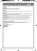
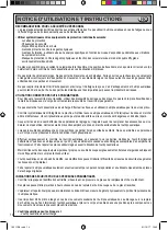
OPERATION MANUAL AND INSTRUCTIONS
EN
KEY TO SYMBOLS
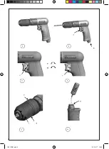
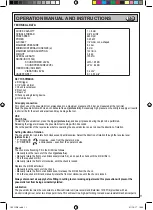
a: Drill trigger
b: 1/4” GAS air inlet
c: Chuck reverse lever
d: Front nut
e: Rear nut
f: Chuck opening/closing device
g: Oil lubrication
Air supply connection
For correct use of the pneumatic tool, always keep to a maximum pressure of 6.2 bar, as measured at the tool inlet.
Feed the pneumatic tool with clean, condensate-free air (picture 2-b). Excessively high pressure or humidity in supply air results
in shorter life for the mechanical parts and may damage the tool.
USE
Start / Stop
To start the pneumatic tool, press the trigger (picture 2-a), and keep it pressed during the job to be performed.
Releasing the trigger will cause the pneumatic tool to stop within 2 seconds.
Check the position of the reverse lever before operating the pneumatic tool, so as to know the direction of rotation.
Setting direction of rotation
The pneumatic tool can rotate both clockwise and anticlockwise. Select the direction of rotation through the reverse lever
(picture 3c-4c):
“ F ” FORWARD clockwise - seen from the operator’s side
“ R ” REVERSE anticlockwise - seen from the operator’s side
Chuck
The chuck is self-locking. Fit in the drill bit as follows:
• Manually lock the rear nut of the chuck (picture 5-e).
• Manually rotate the front nut anticlockwise (picture 5-d), and open the chuck until the drill bit fits in.
• Fit in the required drill bit.
• Manually rotate the front nut clockwise, until the chuck is locked.
Replace the drill bit as follows:
• Manually lock the rear nut of the chuck.
• Manually rotate the front nut anticlockwise, to release the drill bit from the chuck.
• Fit in the required drill bit and manually rotate the front nut clockwise, until the chuck is locked.
Always disconnect air supply before fitting in cutting tools or making adjustments; this precaution will prevent the
pneumatic tool from being accidentally started.
Lubrication
The pneumatic tool must be connected to a filter-lubricator unit (we recommend Beta item 1919F1/4) provided with an
air-oil microfog mixer, set at two drops per minute. This will result in a high-performing tool and wear-resistant mechanical parts.
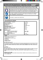
CHUCK CAPACITY
SPINDLE THREAD
FREE SPEED
POWER
AIR INLET
MAXIMUM PRESSURE
MINIMUM INTERNAL HOSE SIZE (ø)
MAXIMUM AIR CONSUMPTION
WEIGHT
OVERALL LENGTH
NOISE (ISO 15744)
SOUND POWER LEVEL
SOUND PRESSURE LEVEL
VIBRATIONS (ISO 28927)
VIBRATION LEVEL
UNCERTAINTY
1 ÷ 6 mm
3/8” 24 UNF
2600 rpm
0.23 kW
1/4” GAS, cone-shaped
6.2 bar
8 mm
130 l/min
0.6 kg
153 mm
LWA = 95 dB
LPA = 84 dB
0.4 m/s
2
K = 0.53 m/s
2
TECHNICAL DATA
1931CD6.indd 11
31/10/17 10:40


