40
ASSEMBLY
betamotor.com
1
1
2
2
4.5 CRANK ASSEMBLY
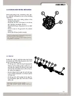
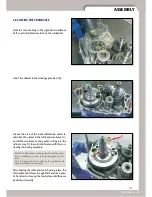
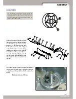
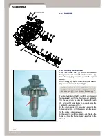
If the crankshaft has been dismantled for the pur-
pose of replacing the connecting rod or inspecting
the state of wear of the roller cage and the crankpin,
be careful during subsequent reassembly that the
oilway holes in the crankpin (A) and in the clutch
side crankshaft half (B) are properly lined up. Faulty
assembly could lead to lack of proper lubrication
in the area of the conrod big-end, with consequent
damage to the roller bearing.
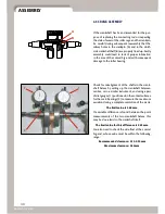
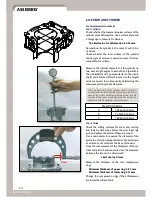
Check for misalignment of the shafts in the crank-
shaft halves by setting up the crankshaft between
centres, or in a similar instrument, and using a pair
of dial gauges (1) positioned on the contact surfaces
for the main bearings (2) to measure the maximum
variation during a complete revolution of the crank.
The limit value is 0.08mm.
If a variable difference is found between the point
measurements of the two crankshaft halves, this
may be due a twist in the crankshaft itself.
The limit value for this difference is 0.03mm.
You also need to check the side-float at the conrod
big-end, whose value must be within the following
range:
Recommended clearance: 0.15-0.35mm
Maximum clearance: 0.50mm
A
B

