background image


[H ie

 Bekamatic SC                                                                                                                                                                                       pg. 10 

 r eingeben]  

[H ier eingeben]  

[H ier eingeben]  


5.


Preparations before gate installation:  


5.1.


Fixing requirements 


Chemical anchors M16 x 250 mm with “Fender” type washers 
(minimum 125 mm anchor depth and minimum 100 mm above finished 
Ground Level). 


For the mounting and securing of: 

-


Guiding post (4 anchors) 

-


Lock post (4 anchors) 

-


Rear guiding roller set (4 anchors) 


Chemical anchors M10 x 200 mm. 4 anchors for the mounting and 
securing of the support roller assembly (when fully open

)


WARNING! 


DO NOT USE MECHANICAL ANCHORS AS THEY ARE NOT 
SUITABLE FOR THIS APPLICATION!


The max distance between the concrete and post base plate should not be more 
than 50mm. Otherwise the stability is reduced.  
(Within the warranty period, should the user report that “the gate does not move 
smoothly” and it is established that the gate position is not correct while this rule 
has not been followed, then the claim will not be accepted).  


5.2.


Installation of the ground anchors: 


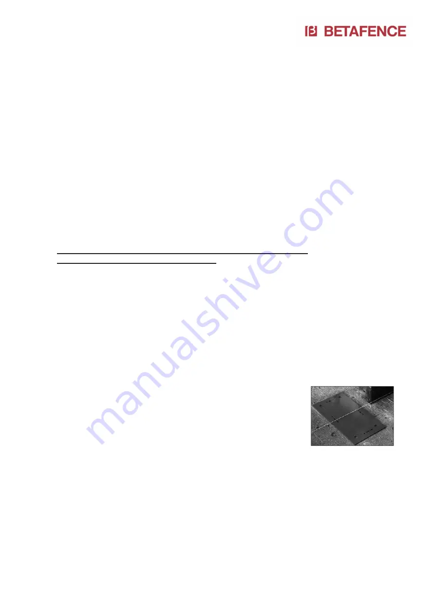
1)


Lay a tension line through the central axis of 
the foundations to indicate the exact position 
where the gate is to be installed. This 
incorporates the lock post, the guide post, the 
rear roller assembly and the rear support 
roller. 


2)


Position the templates for the guiding and lock 
posts and rear roller assembly. Using the 
tension line as a guide, align the center 
markings of the templates, ensure that the 
distances between the templates are adhered 
to as laid down in the foundation plans 
provided with the order document. 


3)


Mark the position of the holes with a small diameter concrete drill. 
This will help to centralize the final drilling to the required diameter. 


Summary of Contents for Bekamatic SC 6000 Line

Page 1: ...Bekamatic SC pg 1 Cantilever sliding gates Bekamatic SC 6000 Line Installation Manual ...

Page 2: ... the gate onto the ground anchors 12 7 Installation of the lock post onto the ground anchors 13 8 Alignment and levelling of the gate 13 9 Adjustment of the mechanical end stops 16 9 1 Adjustment of the front mechanical end buffering 16 9 2 Adjustment of the rear mechanical end buffer 17 10 Motor height Adjustment 18 11 Set up of the end position 20 12 Power Supply 20 13 Adjustment and testing of ...

Page 3: ...ion regulations can vary from country to country Incorrect installation can cause harm to humans animals and foreign objects for which the manufacturer cannot be held responsible In case of a failure and or poor functioning of the equipment apply exclusively only professional qualified personnel ideally the manufacturer or a certified installer Only original spare parts should be used to carry out...

Page 4: ... closed positions to avoid unnecessary wear when coming into contact with the buffers Under extreme weather conditions heavy wind hold the wing securely during the opening or closing of the gate so that uncontrolled movement of the wing can be excluded Persons are not allowed to ride on the wing during operation because of the following crush hazards Between the guiding post and the wing as this c...

Page 5: ...ce in cooperation with the user For gates installed in Germany the user must ensure that every 12 months the gate is inspected as per ASR A 1 7 Once inspected the testing agency raises a report If the gate meets all requirements then this is indicated in the report and a test sticker is applied to the gate If the gate fails then the faults are captured in the report and communicated to the user Th...

Page 6: ...ient lifting capacity 4 Foundations Foundations prepared according to the corresponding drawing For standard range of gates see page 5 and 6 For the drawings and dimensions see page 7 For all non standard executions and gate combinations please consult the special foundation drawings supplied with the gate The gate must not be installed following the slope of the construction site Make sure that t...

Page 7: ...tic SC pg 7 Warning THE FOUNDATION PLANS PROVIDED ON THE FOLLOWING PAGES SERVE ONLY AS AN EXAMPLE ALWAYS USE THE PLANS PROVIDED WITH THE ORDER DOCUMENT Concrete quality C25 cubic pressure resistance 25 N mm2 ...

Page 8: ...Bekamatic SC pg 8 4 1 Gates opening to the right ...

Page 9: ...Bekamatic SC pg 9 4 2 Gates opening to the left ...

Page 10: ...nty period should the user report that the gate does not move smoothly and it is established that the gate position is not correct while this rule has not been followed then the claim will not be accepted 5 2 Installation of the ground anchors 1 Lay a tension line through the central axis of the foundations to indicate the exact position where the gate is to be installed This incorporates the lock...

Page 11: ...ved 5 3 Preparing installation levels 1 Screw the lower adjustment nuts onto their ground anchors some 25mm above the concrete and place the 3D washers onto the nuts 2 Using a spirit level see photo adjust the height of all 4 nuts so that they are horizontal to one and other The guiding post position serves as a reference point for the installation of the other main components Roller assembly lock...

Page 12: ... holds the under beam and base plate together 2 Position the gate with the guiding post above the ground anchors approximately 500mm above the ground 3 Open the main upper access door of the guiding post cabinet Open the small lower door of the guiding post cabinet 4 Identify the cables which go to the end post photocells key switch etc 5 Pull these cables through the cable pipe to the lock post 6...

Page 13: ...uninstalling replacement of photocells 3 Position the lock post onto the ground anchors and install the upper washers with nuts Tighten the nuts slightly for temporary fixation 8 Alignment and levelling of the gate 1 Put the gate in manual disengaged mode by turning the red sling clockwise 2 Align the rear roller assembly and the guiding post according to the gate center axis line Ensure that the ...

Page 14: ...ATE 5 After alignment of the lock post and horizontal levelling of the wing adjust the height of the lock post so that the support wheel under the front of the under beam is just touching the ramp of the lock post Ensure that the vertical level and position in the catcher is maintained The height adjustment is made with the ground anchor nuts ATTENTION The support wheel in the under beam must not ...

Page 15: ... support roller installed too high will add undesired friction to the wing which increases the further the wing is opened 11 The height of the support roller must be adjusted once the wing is approximately 500mm away from the completely open position 12 In this position the support roller should start to contact the under beam Adjust the height as necessary Do not adjust the tensioning system Supp...

Page 16: ...ont buffer does not need to be adjusted as the factory default setting of 60mm will be sufficient However if there is some deviation from the foundation plan or an obstacle at the rear side of the gate prevents the wing opening over its full course then adjust according to the description below 1 Pull the lower part of the safety pressure strip from its aluminum fixation profile 2 Remove the front...

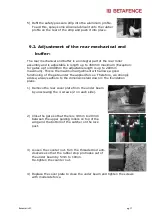
Page 17: ...mum This is the maximum adjustment with allows a good functioning of the gate under the applied forces Therefore we strongly advise always adhere to the dimensions laid down in the foundation plans 1 Remove the rear cover plate from the under beam by unscrewing the 4 screws 2 on each side 2 Close the gate so that there is 10mm to 20mm between the upper guiding rollers on top of the wing and the bo...

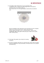
Page 18: ... rear roller assemblies 2 Turn the red sling anti clockwise to engage the motor and gearbox 3 Adjust the height of the pinion by turning the M12 nut allowing the spring to raise the drive assembly upwards Raise until the dental wheel is fully meshed with the dental rack The spring ensures that a good meshing between dental rack and dental wheel is maintained during movement ...

Page 19: ...ck Once the adjustment has been done Move the wing over the complete length of movement observing the dental wheel and rack Should meshing problems occur in certain positions these can be regulated by either moving the dental rack up or down on the under beam oblong holes 5 Disengage the gearbox by turning the red sling clockwise 6 Move the wing back and forth by a small amount Check that the dent...

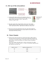
Page 20: ...and closed positions checking that the position of the wing in relation to the LED s in the steering is switching correctly 12 Power Supply 1 Power source must be 230V AC Connect the power supply cable to the main switch connectors There are three connectors foreseen for connection of the power supply The cable from the main board to the gate must be secured according to the latest electrical inst...

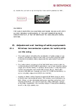
Page 21: ...ns between safety edges and the automation s control board The radio system comprises of an XRS 868 radio receiver able to communicate with XTS 868 transmitters one or two resistive safety edges 8 2 k Ohm XS55 or auxiliary devices N C contacts which can be connected to each transmitter input No 2 Each radio receiver XRS 868 can manage up to 6nr XT S 868 transmitters i e up to 12 safety edges mod X...

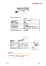
Page 22: ... eingeben Below the technical specifications Receiver Transmitter Important To assure correct work of this system is better that you change every year the batteries To ensure a correct function of the system the batteries must be renewed on a yearly basis ...

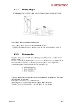
Page 23: ...d on a BUS system They need only two wires without polarity Each set consists of a transmitter and receiver Both devices must be set on the same channel this is achieved by selecting the correct dip switch You can program the photocells so that they work in Closing direction Opening direction Both directions The photocells work in pairs and must be aligned so A maximum of 7 pairs can be fitted to ...

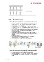
Page 24: ... transmitter and push and hold both buttons until the led on the top of the transmitter starts to flash Release both buttons Choose now on your transmitter the button that you want to program Push this button until the led DL11 illuminates and stays on Release the button Push the programmed button twice in quick succession The second push sets the gate in motion If this happens the programming was...

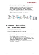
Page 25: ...s If this happens the programming was successful 14 Different Set up systems 14 1 Set up for Bus system This set up has already been done in the factory Every tool that is connected to the bus system must be learnt by the controller The following process describes how this is to be carried out Access BASIC programming with button F and scroll through the functions up until bu When F is released th...

Page 26: ...parameter tL when F is released will appear 2 Ensure that the gate wing s are closed Otherwise proceed as follows 3 Press button R1 to close the gate Should by pressing button R1 the gate wing s open switch off the power and on terminal board J2 invert the phase cables of the corresponding motor s terminals 2 3 for wing motor 4 When the gate wing is closed launch SETUP by pressing and holding and ...

Page 27: ...afence com www betafence de Betafence France SAS 2 rue Alexis de Tocqueville Parc de Haute Technologie F 92183 Antony Cedex Tel 33 1 40 96 26 22 info france betafence com www betafence fr Betafence Schweiz GmbH Hardstrasse 59 S 5432 Neuenhof Tel 41 56 406 90 39 tibor gal betafence com https www betafence ch fr https www betafence ch de https www betafence ch it Betafence Limited P O Box 119 Shepco...

Page 28: ... Hie Bekamatic SC pg 28 r eingeben Hier eingeben Hier eingeben This Manual is made on 13 05 2019 ...

Reviews: