
27
Robusta SC
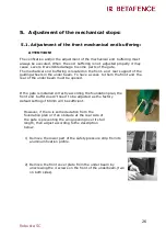
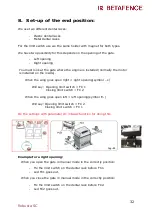
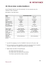
3)
Unlock the counter nut. Turn the threaded rod counter-
clockwise so that the rubber stop is coming out of the
underbeam for 0.5 cm to 1 cm.
Block the threaded rod with the counter nut.
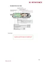
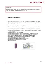
ATTENTION!
Do not turn clockwise.
The default setting of 13 cm is minimum distance to
apply.
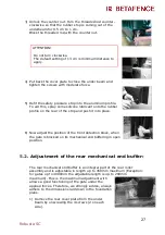
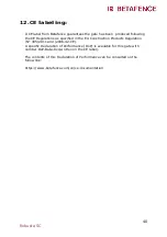
4)
Put back the cover plate to close the under beam and
tighten the screws with moderate force.
5)
Refit the safety pressure strip into the aluminum profile.
To aid this, spray some silicone lubricant onto the rubber
profile on the rear of the strip and push it into place.
6)
Now adjust the position of the front detection block, when
the gate is blocked on its mechanical end buffering in open
position.
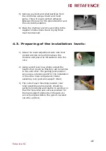
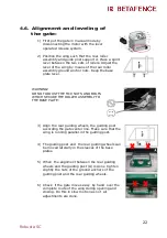
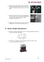
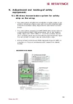
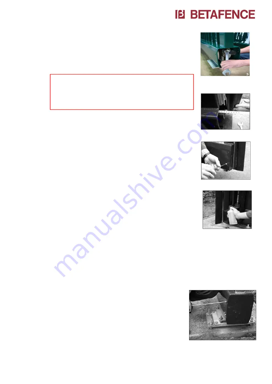
5.2
. Adjustment of the rear mechanical end buffer:
The rear mechanical end buffer is an integral part of the rear roller
assembly and is adjustable in length up to 450mm maximum (Exception:
for gates up to 4000mm the adjustable length is up to 200mm
maximum). This is the maximum adjustment with
allows a good functioning of the gate under the
applied forces. Therefore, we strongly advise, always
adhere to the dimensions laid down in the foundation
plans.
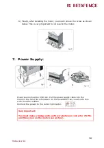
1)
Remove the rear cover plate from the under
beam by unscrewing the 4 screws (2 on each
side).
Summary of Contents for R2000
Page 1: ...1 Robusta SC Cantilever sliding gates Robusta SC Installation Manual ...
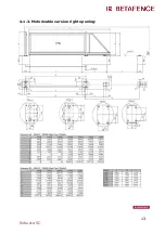
Page 11: ...11 Robusta SC 4 1 1 Automatic version right opening ...
Page 12: ...12 Robusta SC 4 1 2 Automatic version left opening ...
Page 13: ...13 Robusta SC 4 1 3 Motorizable version right opening ...
Page 14: ...14 Robusta SC 4 1 4 Motorizable version left opening ...
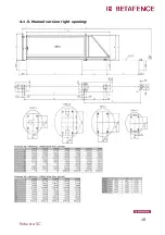
Page 15: ...15 Robusta SC 4 1 5 Manuel version right opening ...
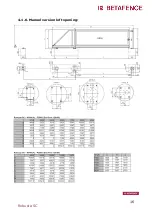
Page 16: ...16 Robusta SC 4 1 6 Manuel version left opening ...


