background image

15

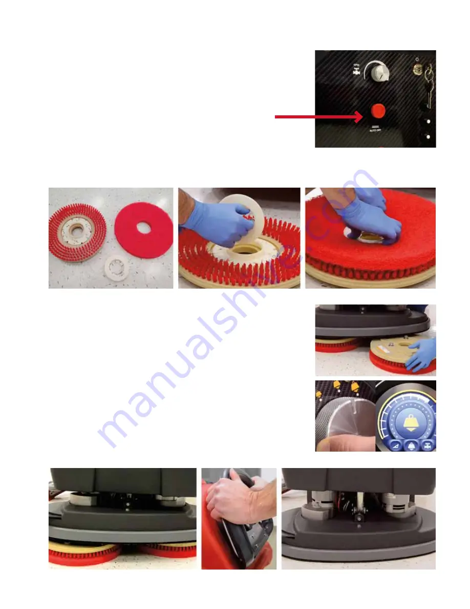
DISK MACHINE PAD DRIVERS AND BRUSHES

PAD AND BRUSH REMOVAL

NOTE: Do not use this machine without a pad or brush. This will damage the machine.

1.  To remove the pad driver, push and hold the red “Auto Off” button in the middle of 

lower control panel. The brushes will release from the brush holders.

2.  To release the pads, press down on the pad and release the wire tabs.

NEW PAD INSTALLATION

1.  Remove the center lock plastic keeper by squeezing the wires inward and pull the 

center lock away.

2.  To connect the new cleaning pad to the drivers, center the pad on the brush, squeeze 

the center wire lock tabs and press down until it clicks.

PAD AND BRUSH INSTALLATION

1.  Place the pad driver assemblies under the scrub deck of the machine. Try to 

align the assemblies under the scrub deck shroud.

2.  Turn the key on and lower the head to medium or second down pressure 

position.

3.  Turn the speed setting to the lowest position.
4.  Slightly push or pull the machine to align the pad drive assemblies to help 

align the attachment lugs.

5.  Pull the bail back to engage the pad drivers to the machine’s pad drive train.
6.  Once the pad drive assemblies are attached, adjust down pressure setting to 

perform desired application.

NOTE: If the pad drivers do not connect the first time return to step 4 and 

repeat.

Summary of Contents for E27200

Page 1: ...S GENESYS SERIES SERIES 26 28 and 32 Mid Size Scrubber Operator and Parts Manual 400 Van Camp Bowling Green Ohio 43402 Customer Service 888 GO BETCO Fax 800 445 5056 Technical Service 877 856 5954 www betco com E27400 E27500 ...

Page 2: ... Inspection and cleaning 13 Scrubbing System Head Lift 14 Selecting Down Pressure 14 Disk machines Pad Drivers and Brushes 15 Auto Off Pad driver 15 Orbital Pads 16 Recovery System Draining the Tank 17 Recovery Tank 17 Debris Tray 18 Fortify Foam Control De Foaming Chemical Puck 18 Squeegee Assembly Cleaning 19 Drip Trap 19 Inspecting 19 Selection Guide 20 Remove and Install 20 Operating Lever 21 ...

Page 3: ...5 dBa 65 dBa 65 dBa 65 dBa Vac Motor Filter 72 HP HEPA 72 HP HEPA 72 HP HEPA 72 HP HEPA Machine Weight w 260AH Batteries 625 lb 630 lb 640 lb 630 lb Machine Dimensions 55 in x 28 in x 44 in 56 in x 30 in x 44 in 59 in x 34 in x 44 in 54 in x 29 in x 44 in Squeegee Width 35 in 40 in 45 in 40 in Warranty 10 Years Rotomold 3 Years Parts Labor 180 Days Travel 1 Year Pro rated Batteries 10 Years Rotomo...

Page 4: ...er in case of fire Do not use water Do not hit against shelving or scaffolding The operator must always be equipped with the appropriate safety device gloves shoes helmet glasses etc Do not use the machine on surfaces with an inclination greater than the one shown on the serial plate The machine is designed to wash and dry floors simultaneously Signal the presence of wet floors with suitable signs...

Page 5: ...pose Even the best machines will only work well if used correctly and kept in good working order We therefore suggest you read this instruction booklet carefully and re read it whenever difficulties arise while using the machine Please contact our technical service department or your dealers if you have any questions about the machine 1 Remove the outer packing from the machine s shipping pallet F...

Page 6: ...ngle for easy ramping STEP 1 Before transporting up a trailer ramp remove the squeegee assembly and put it in an open secure location on the trailer If possible wrap with a shipping blanket STEP 2 Transport machine up the ramp into trailer and position it so that tie downs can be used forward and rear of the machine and lower the scrub deck with pads on especially the Orbital STEP 3 Open the tank ...

Page 7: ...ed in the machine as shown for ease of wiring the batteries in series When replacing batteries make sure to position the batteries in the same configuration LEAD ACID WET BATTERIES ONLY Wet batteries need water More importantly watering must be done at the right time and in the right amount or the battery s performance and longevity suffers Water should always be added after fully charging the bat...

Page 8: ...jug of distilled water and prime the pump bulb by squeezing it until it is filled with water 2 Attach the other end of the hose to the quick connect already on the batteries 3 Squeeze the bulb to pump water into the battery cells When the bulb becomes firm all cells are full Note Battery packs equipped with Fortify Wet Battery Protection may use more distilled water than expected to make the light...

Page 9: ...s Red LED is on First phase of charging is in progress Yellow LED is on Second phase of charging is in progress Green LED is on End of charge or maintenance phase Yellow LED is flashing Issue with battery or battery not connected or output short circuit Red LED Flashing Safety timer exceeded internal short circuit Green LED Light Yellow LED Light Red LED Light Note Do not use an extension cord Thi...

Page 10: ...reaker This might require a cooling down period of the machine s tripped component before the breaker is allowed to be reset BATTERY METER When the machine s key is switched to the ON position the battery meter gives a readout of the charge remaining on the battery pack LED lights will reduce in number as the charge on the batteries goes down Note A flashing battery meter will indicate a fault SQU...

Page 11: ...e the machine push the bail wire away from the console handle To slow down or stop simply release the bail 3 The centralized Speed Control Knob on the console handle is used to reduce or increase the machine s speed This can be done while moving or standing still 4 Touch Encoder equipped machines can limit the top speed of the control knob NOTE Use good judgment when selecting a higher speed Turn ...

Page 12: ...use pure acids in this machine FILLING SOLUTION THE TANK 1 Add water to the solution tank from the front or rear fill locations Do not use water exceeding 120 F 48 9 Celcius 2 While filling the machine watch the sight tube on the back of the machine to determine when the machine is full CONVENTIONAL OPERATION 1 Remove the SoliChem solid from the solution system This can be done by lifting the reco...

Page 13: ...r Touch Encoder machines adjusting flow rate is found in the settings FILTER INSPECTION AND CLEANING NOTE If there is excessive debris found in the screen and bowl then drain and flush the solution tank 1 Close the shutoff valve for the solution tank The screen and bowl are under the frame between the transaxle and casters on the left side of the machine 2 Unscrew and remove the filter bowl and sc...

Page 14: ...d bristle skirt that virtually eliminates overspray SELECTING DOWN PRESSURE 1 Low pressure 60 lb Daily cleaning of normal soils 2 Medium pressure 120 lb Heavy soils or chemical free finish removals 3 High pressure 180 185 lb Heavy soils orbital finish removal or chemical stripping MACHINE OPERATIONAL SETTINGS 26 Disk 28 Disk 32 Disk 28 Orbital Low 60 60 60 60 Medium 120 120 120 120 High 180 185 18...

Page 15: ...r the pad on the brush squeeze the center wire lock tabs and press down until it clicks PAD AND BRUSH INSTALLATION 1 Place the pad driver assemblies under the scrub deck of the machine Try to align the assemblies under the scrub deck shroud 2 Turn the key on and lower the head to medium or second down pressure position 3 Turn the speed setting to the lowest position 4 Slightly push or pull the mac...

Page 16: ...and variances in the floor The maroon pad is for surface preparation 1 Attach the red pad to the orbital pad drive plate as shown above 2 Place the pad on the floor and position it so that when the scrub deck is lowered the red and maroon pad aligned and stacked MACHINE SETUP FOR ORBITAL FINISH REMOVAL 1 Install the pad assembly as described above 2 Fill the solution tank with clean water 3 The do...

Page 17: ... collar into the drain slowly 4 Lift the recovery tank lid to the wide open position CLEANING THE RECOVERY TANK WHEN DRAINING 1 Rinse out the recovery tank often to prevent debris dirt buildup and any contaminants 2 Use a hose to remove debris and sediment from the bottom of the tank with clean water Note Regularly use cleaner and sanitizer with a cloth or sponge to prevent mold and mildew inside ...

Page 18: ... the recovery tank lid Remove the debris tray and flip it over 2 Turn the puck cage counter clockwise to release it from the debris tray Replace puck as needed Return debris basket to recovery tank Caution Do not use chlorine Harmful fumes can be created from mixed cleaners and chlorine RECOVERY LID Leave the recovery lid open while in storage and after cleaning This enables the recovery tank to d...

Page 19: ... any water and loose debris DRIP TRAP INSPECTION 1 Inspect the drip trap on the topside of the squeegee by removing the 2 thumb screws 2 Rinse off the drip trap and remove any debris 3 Wipe and clean the squeegee frame before re installing the drip trap SQUEEGEE BLADES INSPECT 1 Inspect the front and rear squeegee blades The forward edges should be sharp and defined 2 Worn blades should be flipped...

Page 20: ...e Airoflex valve Floor Type Suggested Squeegee Comments Vinyl Composite Tile VCT Grouted Tile Natural Stone Terrazzo Polished Sealed Concrete Wood LINATEX Best combination of performance durability and wear life Luxury Vinyl Tile LVT Rough Concrete LINATEX or PRIMOthane Both will have good performance Primothane will last longer if floor is highly textured Rubber Other Non Slip Grit Surfaces PRIMO...

Page 21: ...e squeegee Move the squeegee lever to the right The vacuum motor will come on 2 Raise the squeegee Move the squeegee lever to the left The vacuum motor will turn off after 7 seconds SQUEEGEE HEIGHT ADJUSTMENT No adjustment Factory set ...

Page 22: ...nfo and register device NOTE The machine data will appear in the armordata com dashboard on the next business day The included 12 month free subscription will start once this process is complete OPERATION The data that is logged by the ARMOR device can be viewed from any computer that has an internet connection The device automatically sends its data once every day and after every charge discharge...

Page 23: ...oth download the ProView Link app by Pro Charging Systems from either Google Play or the Apple App Store The device must have Bluetooth enabled and must be in Bluetooth proximity to access it Upon launching the app a list of gauges that are in range of Bluetooth device will be shown This overview shows the name of the gauge the current pack voltage the nominal system voltage signal strength and cu...

Page 24: ...d to ON OFF and AUTO by pressing the MANUAL button The machine can only be operated when the red light is illuminated on the timer If the machine is to be used outside of the programmed time the manual button can be pressed until ON is displayed Ensure that the machine is turned back to AUTO to re enable the programs ON The machine is active and will not be disabled at any time OFF The machine is ...

Page 25: ...25 ...

Page 26: ...26 FRAME DIAGRAM 39 38 34 6 2 30 29 4 28 37 2 30 5 31 33 32 35 31 9 33 32 33 25 24 36 14 25 10 36 31 33 31 25 8 33 18 11 10 12 13 10 36 23 17 21 15 19 20 27 26 22 27 3 16 33 1 37 7 37 ...

Page 27: ...0 75 Shaft x 0 046 Groove 1 19 E28759 Squeegee Lift Cable 1 20 E28762 Screw Socket Head 4 40 x 1 0 LG 2 21 E28763 SCREW FLAT HEAD 3125 18 x 1 0LG 1 22 E28770 Nut Nyloc 4 40 2 23 E28909 Squeegee Lift Lever 1 24 E28936 Sleeve Bearing 2 25 E28937 Washer 0 50 505ID 75OD 0 067T Nylon 4 26 E28952 Micro Switch 1 27 E29368 Washer No 4 125ID 312 OD 03 HD HT 4 28 E29388 Washer 3125 344 ID 1 0 OD 4 29 E29400...

Page 28: ...28 SQUEEGEE DIAGRAM 9 15 14 12 19 8 5 16 7 10 1 3 4 20 2 18 11 13 15 9 17 10 6 6 ...

Page 29: ...ear Squeegee Blade 45in 1 12 1 E28502 Rear Squeegee Blade 40in 1 12 2 E29450 Rear Squeegee Blade 35in 1 13 E29456 Front Squeegee Clamp Assembly 45in 1 13 1 E29520 Front Squeegee Clamp Assembly 40in 1 13 2 E29451 Front Squeegee Clamp Assembly 35in 1 14 E29457 Rear Squeegee Clamp Assembly 45in 1 14 1 E29517 Rear Squeegee Clamp Assembly 40in 1 14 2 E29452 Rear Squeegee Clamp Assembly 35in 1 15 E29521...

Page 30: ...30 DISK HEAD LIFT DIAGRAM 19 32 33 17 10 20 22 29 25 42 2 41 23 40 21 18 11 34 24 23 31 16 30 39 6 15 43 2 11 28 2 13 14 5 2 4 11 2 26 8 2 3 35 2 9 7 1 12 42 36 38 37 27 ...

Page 31: ...20 E28769 Screw SHCS 4 40 x 875 LG 2 21 E28770 Nut Nyloc 4 40 6 22 E28778 TDS Shield Bracket 1 23 E28779 Screw SHCS 4 40 x 4375 LG 8 24 E28780 Washer Split No 4 6 25 E28782 Screw SHCS 4 40 x 1 25 LG 2 26 E28783 Pin Clevis 5 16 x 3 Lg 1 27 E28784 PCB TDS Sensor 1 28 E28822 Bolt Hex 313 18 x 2 5 Lg Grade 8 2 29 E29000 Actuator Mounting Bracket Weldment 1 30 E29002 Switch Cam 3 31 E29003 Clevis Pin 0...

Page 32: ...32 ORBITAL HEAD LIFT DIAGRAM 24 36 22 33 25 39 12 37 44 28 27 43 26 30 4 23 13 21 35 34 38 29 28 42 7 46 32 4 16 17 6 20 2 14 5 18 4 10 11 5 4 8 3 4 9 45 4 45 2 1 5 4 15 19 19 40 31 41 ...

Page 33: ...t Weldment 1 22 E28727 Compression Spring Upper 2 23 E28728 Compression Spring Lower 2 24 E28730 Screw Shoulder 0 5 Dia 0 375 16 x 4 25 LG 2 25 E28769 Screw SHCS 4 40 x 875 LG 2 26 E28770 Nut Nyloc 4 40 6 27 E28778 TDS Shield Bracket 1 28 E28779 Screw SHCS 4 40 x 4375 LG 8 29 E28780 Washer Split No 4 6 30 E28782 Screw SHCS 4 40 x 1 25 LG 2 31 E28784 PCB TDS Sensor 1 32 E28822 Bolt Hex 313 18 x 2 5...

Page 34: ...34 ORBITAL HEAD DIAGRAM 32 5 4 41 23 37 14 21 35 23 38 34 25 23 1 23 25 22 33 14 25 23 29 2 31 23 24 19 44 40 7 9 17 15 16 28 13 10 36 3 46 45 30 6 8 27 11 12 18 20 39 43 26 42 ...

Page 35: ...e Tie Push Mount 2 23 E28622 Washer 0 313 0 344ID 0 750OD 0 050T SS 16 24 E28623 Nut Hex 0 313 18 Thin Nyloc SS 2 25 E28624 Nut Hex 0 313 18 Nyloc SS 8 26 E28631 Hub Washer 1 27 E28632 Retaining Ring Int 90mm Bore x 3 15mm Groove 1 28 E28633 Isolator Spacer 4 29 E28634 Screw Flat Hd 0 313 18 x 1 75 Lg Hex Drive 2 30 E28635 Machine Key 8mm x 7mm x 28mm 1 31 E28640 Washer Spring Acetal 0 451 I D X 0...

Page 36: ...36 SOLUTION TANK DIAGRAM 2 17 26 1 28 13 15 3 29 25 30 6 9 30 27 8 14 10 15 13 7 6 11 24 15 13 12 5 31 16 22 23 19 18 21 20 32 AGM WET 4 IT ...

Page 37: ...28765 Washer Wave 32 ID 0 437 OD 1 15 E28775 Washer No 10 0 203 ID 0 438 OD SS 6 16 E28785 Battery Spacer Foam 1 17 E28959 Battery Tray 1 18 E28974 Fuse Holder 1 19 E28975 Fuse 1 20 E29201 Battery Cable 34 1 21 E29202 Battery Cable 23 1 22 E29203 Battery Cable 12 3 23 E29204 Battery Cable 5 1 24 E29305 Fitting Barbed Tube 3 4 ID x 3 4 Male NPT Plastic 1 25 E29388 Washer 3125 344ID 1 0OD 4 26 E2939...

Page 38: ...38 DISK HEAD DIAGRAM 26 10 11 21 7 7 12 20 5 8 9 6 3 15 19 18 16 22 23 24 4 17 25 2 7 27 11 14 1 13 27 27 28 8 ...

Page 39: ... 13 2 E29341 Disk Head Skirt Assembly 26 1 14 E29385 Washer Lock 6mm 14 15 E29389 Machine Key 5mm x 5mm 2 16 E29390 t Hex 10 24 x 375 Lg 4 17 E29391 ew Flat Hd 0 25 20 x 375 Lg Hex Drive 12 18 E29426 Bolt Hex M8 x1 25 25 00 Lg 2 19 E29438 Washer M8 8 4mmID 22mmOD 4 5mmT SS 2 20 E29513 Bolt Hex 0 3125 18 x 1 75 Lg 1 21 E29514 Lift Arm Pivot Bracket 2 22 E29515 Spring Clip Support 2 23 E29518 Disk L...

Page 40: ...40 RECOVERY TANK DIAGRAM 3 21 18 24 22 31 23 25 26 14 10 15 1 5 20 7 4 17 16 27 28 30 2 1 28 8 6 19 29 9 9 ...

Page 41: ...921 Recovery Tank Drain Hose 1 15 E29392 Bolt Hex 3125 18 x 1 00 Lg 1 16 E29523 Vacuum Mount Bracket 1 17 E29524 25 20 Dual Stud Isolator 3 18 E29525 Debris Tray 1 19 E29526 CreteRx Debris Sock 1 20 E29527 HEPA Filter 1 21 E29528 Recovery Tank Lid Seal 7 22 E29531 1 5in Barbed Tube Fitting 1 23 E29558 Screw Shoulder 313 18 375OD x 2 25 Lg 2 24 E29561 Defoaming Chemical Puck Holder 1 25 E29562 Floa...

Page 42: ...42 SOLUTION SYSTEM DIAGRAM 10 1 27 39 35 24 36 33 4 15 34 25 12 44 38 37 11 25 40 7 37 14 45 6 2 3 17 45 13 22 8 31 32 32 41 16 5 21 28 18 30 19 23 29 23 23 23 9 42 26 22 20 43 ...

Page 43: ... E28751 Hose Fitting_375 Barb and_5 Pipe 1 21 E28752 Hose Fitting_75 Barb and_Pipe 1 22 E28753 Nut Nylon Lock 10 24 SS 6 23 E28766 Clamp Hose 875 to 1 25 x 3125w 5 24 E28767 Washer Fender 406 ID x1 25 OD 1 25 E28773 Clamp Single Pinch 9 26 E28775 Washer NO 10 0 203ID 0 438OD 0 03T SS 4 27 E28786 Hose Fitting Elbow 375 x 25 NPT 1 28 E28922 75 ID Hose 25FT 29 E28922 01 75 ID Hose 4FT 30 E28922 02 75...

Page 44: ...44 CONSOLE DIAGRAM 2 3 26 7 32 31 5 15 9 16 17 28 24 1 23 32 31 27 11 20 18 19 8 29 6 30 10 21 14 22 25 4 BLUETOOTH VERSION 33 ...

Page 45: ...Ext Tooth 4 15 E28915 Handle 1 16 E28955 Potentiometer Speed Control 1 17 E29301 Handle Back 1 18 E29322 Cluster Panel 1 19 E29323 Rotary Switch 1 20 E29324 Down Pressure Knob 1 21 E29325 Handle Bracket Weldment 1 22 E29326 Bail Pivot 1 23 E29327 Handle Bail Arm 1 24 E29328 Spring Compression 5 OD 376 ID 75 LG 2 25 E29329 Screw Hex 3125 18 x 2 LG 1 26 E29334 Screw Torx Head No 8 Thread Forming for...

Page 46: ...TRICAL ENCLOSURE DIAGRAM 34 14 31 1 40 15 30 29 32 20 19 28 38 33 7 39 18 2 21 3 5 25 26 5 8 41 10 38 27 17 12 35 11 4 24 6 3 13 37 3 4 22 22 23 OUTER ELECTRICAL ENCLOSURE INNER ELECTRICAL ENCLOSURE 3 36 5 16 ...

Page 47: ... 21 E28967 Auto on off Button 1 22 E28979 Charger Harness 1 23 E29200 Machine Harness Standard Disk 1 23 1 E29210 Machine Harness Standard Orbital 1 23 2 E28817 Machine Harness Premium Disk 1 23 3 E28818 Machine Harness Premium Orbital 1 24 E28978 40A Relay 1 25 E29363 Plate Timer Armor Cover 1 26 E29364 Plate Timer Cover 1 27 E29366 Nut Hex 10 32 Nyloc Thin ZP 4 28 E29367 Screw Button Hd 10 32 x ...

Page 48: ...Cord SOLUTION TANK X X X X X E28785 Battery Spacer Foam SOLUTION TANK X X X X X E29571 Disk Head Shroud 26 DISK HEAD X X E29536 13in Malish Brush Assembly DISK HEAD X X X E29537 13in Malish Pad Driver Assembly DISK HEAD X X X E29570 Disk Head Shroud 28 DISK HEAD X X E29534 14in Malish Brush Assembly DISK HEAD X X X E29535 14in Malish Pad Driver Assembly DISK HEAD X X X E29572 Disk Head Shroud 32 D...

Page 49: ...PECT DEBRIS TRAY RECOVERY SYSTEM X VERIFY DRAIN HOSE CAP IS SEALED TIGHT WHEN INSTALLED RECOVERY SYSTEM X INSPECT LID SEAL RECOVERY SYSTEM X INSPECT REPLACE DEFOAMER PUCK AS NEEDED RECOVERY SYSTEM X INSPECT HEPA FILTER RECOVERY SYSTEM X CLEAN AND SANITIZE RECOVERY TANK RECOVERY SYSTEM X BATTERIES AND CHARGER INSPECT CABLES TERMINALS FOR CORROSION SECURITY DAMAGE BATTERIES X SERVICE LEAD ACID BATTE...

Page 50: ...ALLOW 7 SECONDS TO SHUT DOWN RECOVERY SYSTEM VACUUM RELAY MAT BE FAULTY CONTACT SERVICE TECHNICIAN TO TROUBLESHOOT AND ISOLATE WIRING DIAGRAM SCRUB HEAD WILL NOT RUN SCRUB HEAD WILL NOT RAISE LOWER SCRUB HEAD SCRUB DECK SETUP BATTERY PROTECTION IS INDICATING LOW WATER SERVICE THE BATTERIES BATTERIES BATTERIES ARE LOWER THAN ALLOWABLE CHARGE BATTERIES CHARGING CIRCUIT BREAKER FOR THE BRUSH MOTORS I...

Page 51: ...51 ...

Page 52: ...y Kawasaki Subaru for a period of 2 years against manufacturer defects All other components except wear items are warranted by Betco for a period of 3 years Wear Items exempt from Warranty consideration include but may not be limited to power cords transport wheels vacuum bags belts squeegee blades pad drivers clutch plates handle grips filters screens throttle cables brushes and carbon brushes Su...

Reviews: