


35
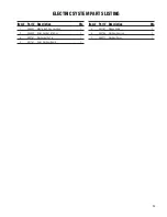
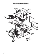
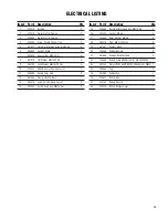
ELECTRICAL LISTING
1
E20272 Bushing
2
2
E20579 Protective Trim Edging
2
3
E20050 Protective Trim Edging
1
4
E20393 Screw, Pan Hd Phil Self Tap
2
5
E81672 Flat Hd SL Machine Screw M3x10 SS
8
6
E83852 Hex Nut, M6x5
2
7
E82808 Hex Jam Nut, M8X5 Zinc
4
8
E81979 Flat Washer M3x7x0.5 SS
4
9
E83704 Lock Washer M8x13x2.2 Zinc
4
10
E20347 SB50 Blue Electrical Connector
1
11
E88090 Handle Enjoy 365
2
12
E81565 Clamp, 4.8x200 Black
1
13
E82376 Latch, Catch & Clasp 2pc set
2
14
E20254 Soc Hd Cap Screw M8x16 Zinc
4
15
E20363 Flat Hd SL Machine Screw M5x12 SS
4
16
E20322 Hex Nut, M5 SS
4
17
E20435 Nyloc Hex Nut, M3 SS
8
18
E83476 Rivet, M6.4x10 Nylon
4
19
E81537 Contact, SB50
2
20
E20568 Rubber Bumper
4
21
E81896 Carriage Bolt M6x16 SS
2
22
E20680 Battery Cable SB50 Blue After S/N 209XXXXX
1
23
E81544 Charger 12VDC 6AMP 120VAC ONB AGM GEL BSB50 1
24
E20586 Cap
2
25
E81969 Rubber Cap
1
26
E20621 Battery Box
1
27
E20167 Battery Box Lid
1
28
E20415 Battery Charger Cover
1
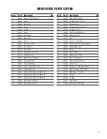
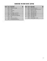
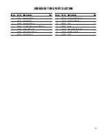
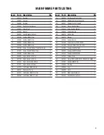
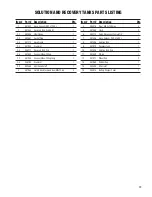
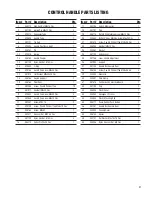
Item# Part # Description
Qty.
Item# Part # Description
Qty.
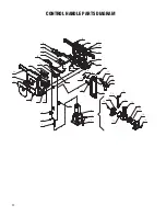
Summary of Contents for Genie B
Page 19: ...19 ...
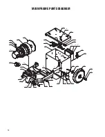
Page 22: ...22 SQUEEGEE SYSTEM PARTS DIAGRAM 5 18 7 1 8 16 15 11 2 3 6 4 17 17 2 12 9 10 11 12 11 14 13 ...
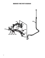
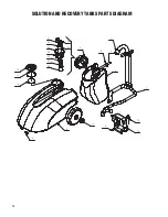
Page 24: ...24 SQUEEGEE YOKE PARTS DIAGRAM 13 2 5 1 10 7 3 11 14 8 6 12 4 9 ...
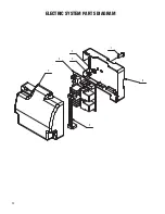
Page 32: ...32 ELECTRIC SYSTEM PARTS DIAGRAM 4 7 2 1 6 3 5 ...
Page 38: ...38 ...
Page 39: ...39 ...


