


9
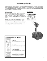
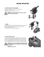
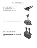
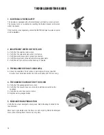
1. MACHINE OPERATION
Before operating the machine:
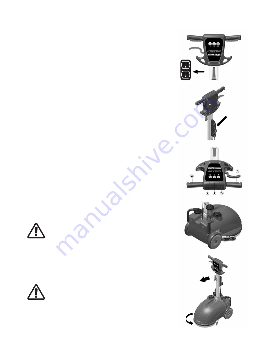
A. Ensure all switches are in the off (“0”) position.
B. Plug the power cord into a grounded wall outlet.
C. Lower the squeegee control lever.
D. Turn on main switch (
1
) and verify that the green indicator light comes on.
E. Turn on the vacuum switch (
2
).
F. Turn on the solenoid valve switch (
3
).
G. At this point the machine is ready for operation. The operating lever will turn
on the brush motor (
4
).
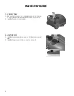
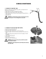
2. OVERFLOW DEVICE
The machine has a float in the filter basket that stops vacuum airflow when the
recovery tank is full. When this happens the recovery tank must be emptied.
WARNING: Always wear gloves when doing this operation to pro-
tect yourself from contact with hazardous chemicals.
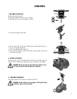
3. FORWARD MOVEMENT
Forward movement of the machine is assisted by the brush.
WARNING: Always make sure the squeegee is lifted when moving
backwards, even for short distances.
OPERATION
Summary of Contents for GENIE CE HD APS
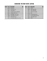
Page 18: ...18 SQUEEGEE SYSTEM PARTS DIAGRAM 6 3 4 13 14 12 11 5 18 1 7 10 8 8 18 15 16 5 9 5 17 2 9 ...
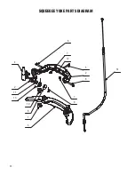
Page 20: ...20 SQUEEGEE YOKE PARTS DIAGRAM 4 2 11 13 10 6 7 5 2 6 7 9 14 12 8 3 1 ...
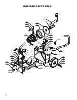
Page 28: ...28 ELECTRIC SYSTEM PARTS DIAGRAM 2 6 4 3 5 3 7 10 2 9 1 8 ...
Page 30: ...30 ELECTRICAL DIAGRAM ...
Page 31: ...31 ...


