Operating Procedures
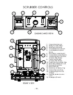
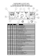
(See page 19 for guide to item numbers)
x
Batteries need to be in the operating range (the green area) of the battery
condition meter (item 2). Gauge will register battery condition when brush motors
(Brush Motor Control Switch, item 6) are turned on. Turn off brush motors after
battery condition is determined.
x
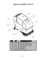
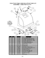
Lift solution lid (item A) and add water and liquid cleaner to solution tank (item B).
Consult cleaner instructions for proper ratio of cleaner and water (Note: the
solution tank holds 24 gallons when full).
x
Take scrubber to area to be cleaned
o
Traction Scrubber
Make sure that squeegee and brushes are off the floor.
Turn variable speed control knob (item 8) all the way
counterclockwise.
Turn on traction switch (item 9).
Squeeze forward control lever (item 1) if scrubber needs to go
forward and reverse control lever if scrubber needs to be moved
backward.
Gradually increase variable speed control knob (item 8) until
scrubber attains the needed speed.
Release lever to stop.
o
Brush Drive Scrubber
Lift squeegee and brushes off the floor.
Push scrubber to desired location.
x
Lower brushes by depressing brush lift pedal (item 13) and then push in on brush
lift and pressure lever (item 11), and gradually let brushes drop to contact with
floor by slowly lift foot off brush lift pedal (item 13). (Note that the brushes can be
lowered using only the brush lift and pressure lever (item 11)).
x
Lower squeegee using the squeegee lift lever (item 18) and turn on vacuum
using the vacuum motor control switch (item 7).
x
Turn on solution by adjusting cleaning solution control lever (item 17) to desired
flow rate (the flow rate can be adjusted as the need arises).
x
Turn on brushes using the brush control switch (item 6) and immediately move
scrubber forward.
o
Traction Scrubber – adjust speed as needed with the variable speed
control knob (item 8).
o
Brush Drive Scrubber – push to desired speed. There is no need to keep
the forward control lever depressed. The brush drive scrubber should
move easily by pushing alone.
Operating procedures are continued on the next page
- 16 -
Summary of Contents for PowerBuff AS2600T
Page 1: ......
Page 2: ... 2 ...
Page 32: ...MOTOR FRAME AND MOTOR MOUNT 15 1 2 3 10 9 4 5 6 7 8 11 12 13 32 ...
Page 48: ......
Page 49: ......


