

10
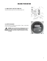
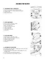
11. INSTRUMENT PANEL COMPONENTS
The instrument panel components are identifi ed as follows:
A. Levers to activate brushes / traction (located beneath the grip)
B. ON/OFF key switch
C. Battery level / hour meter
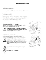
12. REAR COMPONENTS
The rear components are identifi ed as follows:
A. Foot pedal to raise the brush deck
B. Water / solution level hose
C. Drain hose with recovery tank cap
D. Latch to close the tanks
E. Storage compartment
F. Lever to raise the squeegee
G. Solution fi lter
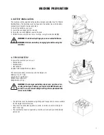
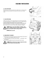
13. SIDE COMPONENTS
The side components are identifi ed as follows:
A. Valve for manual regulation of clean water outlet
B. Handle to raise the recovery tank
C. Handle to raise the vacuum unit
D. Upper storage compartment
E. Brake lever
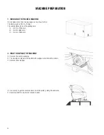
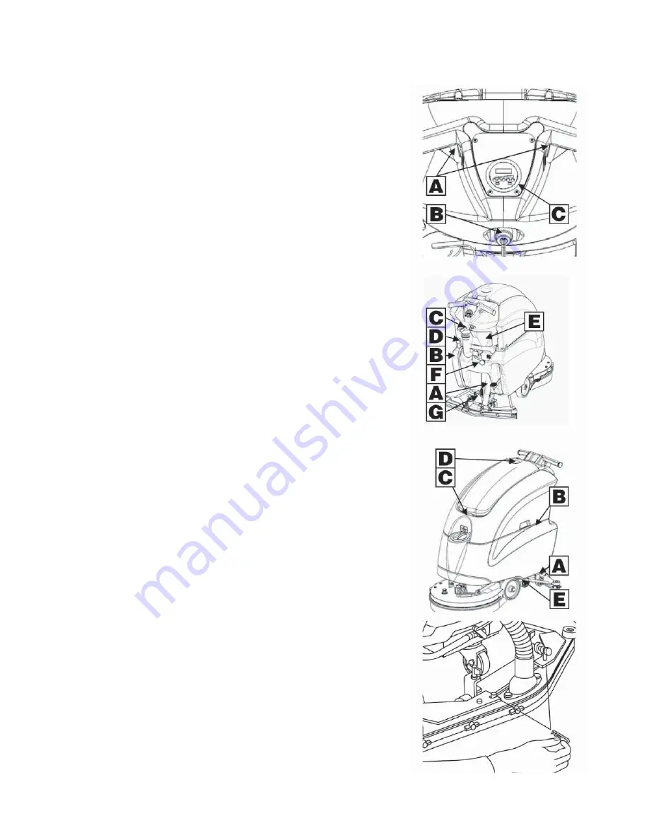
14. ASSEMBLING THE SQUEEGEE
For packaging reasons, the squeegee is supplied dismounted from the machine,
and must be assembled as follows:
A. Insert the two small pins of the squeegee in the appropriate holes on the
squeegee support;
B. Insert the two cotter pins chained to the squeegee;
C. Plug the squeegee hose into the squeegee shoe adaptor.
MACHINE PREPARATION
Summary of Contents for STEALTH ASD20B
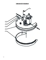
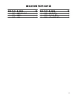
Page 20: ...20 BRUSH DECK DIAGRAM ...
Page 26: ...26 SQUEEGEE YOKE DIAGRAM ...
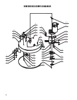
Page 36: ...36 SOLUTION DELIVERY DIAGRAM 8 ...
Page 50: ...50 ...
Page 51: ...51 ...


