64
BRUSH BASE ADJUSTMENT
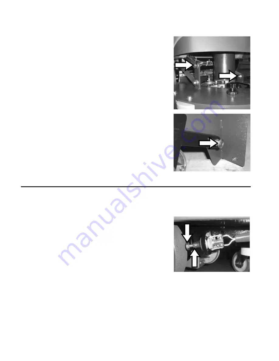
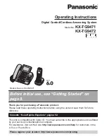
Verify the right inclination of the brush deck adjust. To adjust the brush deck
adjust as follows:
• Lower the brush deck to the floor with a brush installed.
•
Loosen the M8 bolt and the M8 nut
that attach the brush deck to the left
arm.
•
Loosen the nut and the bolt
that attach the brush deck to the idler arm.
• Verify that the brush deck correctly lays on the floor and the brush touches
the floor completely.
•
Tighten the nut and its M8 bolt
to lock the left arm of the brush deck.
• Lift up the front side of the brush deck to let it be 5 mm from the floor relative
to the back side.
•
Tighten the M8 nut
to secure the brush deck in position.
Check that the
pan head screw
on the back side is adjusted near the flat part of
the brush deck. The distance between the screw head and the brush deck has to
be 1 - 2 mm when the brush is locked and the brush deck is lowered.
BRAKE ADJUSTMENT
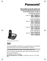
1. Verify that the brake on the left hand wheel locks the wheel when active.
2. Otherwise adjust as follows:
• Unscrew the
jam nut.
• Loosen the
pad screw
to achieve the right adjustment.
• Verify the adjustment with a functional test
• Tighten the
jam nut
to assure a right adjustment.
Summary of Contents for Stealth ASD20BT
Page 22: ...22 BRUSH DECK DIAGRAM BEFORE SERIAL NUMBER 214999999 ...
Page 34: ...34 SQUEEGEE YOKE DIAGRAM BEFORE SERIAL NUMBER 214999999 ...
Page 38: ...38 MAIN FRAME DIAGRAM BEFORE SERIAL NUMBER 214999999 ...
Page 50: ...50 SOLUTION DELIVERY DIAGRAM 2 4 2 8 7 1 5 2 2 3 ...
Page 56: ...56 ELECTRICAL DIAGRAM BEFORE SERIAL NUMBER 214999999 ...
Page 58: ...58 ELECTRICAL DIAGRAM AFTER SERIAL NUMBER 215000000 ...
Page 66: ...66 ...
Page 67: ...67 ...


