

Form Title:
Document #:
INSTALLATION AND MAINTENANCE MANUAL
MM-AD001
(Form: DEF-006A-1)
Revision:
4
Document Title:
Date:
Air Commander™ Air Distributor
Oct. 23, 2017
Page:
1 of 8
Betts Industries Inc.
▪
814·723·1250
▪
1800 Pennsylvania Ave. West
▪
Warren, PA 16365
▪
www.BettsInd.com
Print Date: 10/23/2017
This form is considered uncontrolled 24 hrs. after print date.
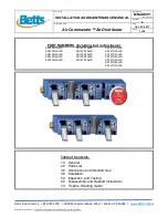
PART NUMBERS
(Including, but not inclusive)
AD14PH1ALFS
AD14PP1ALFS
AD14TO1ALFS
AD14PH2ALFS
AD14PP2ALFS
AD14TO2ALFS
AD14PH3ALFS
AD14PP3ALFS
AD14TO3ALFS
AD14PH4ALFS
AD14PP4ALFS
AD14TO4ALFS
AD14PH5ALFS
AD14PP5ALFS
AD14TO5ALFS
AD14TO6ALFS
AD14TO7ALFS
Table of Contents:
1.0 General
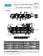
2.0 Parts List
3.0 Description and Intended Use
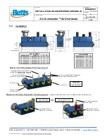
4.0 Installation
5.0 Inspection and Testing
6.0 Disassembly and Rebuild Instructions
7.0 Trouble Shooting Guide


