background image


Form  Title: 

Document  #: 

INSTALLATION AND MAINTENANCE MANUAL 

MM-AD001 

(Form: DEF-006A-1) 

Revision: 

4


Document  Title: 

Date: 

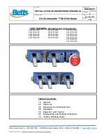
Air Commander™ Air Distributor 

Oct. 23, 2017 

Page:


5 of 8


Betts Industries Inc.   

   814·723·1250    

   1800 Pennsylvania Ave. West   

   Warren, PA 16365   


www.BettsInd.com


Print Date:  10/23/2017   

This form is considered uncontrolled 24 hrs. after print date.
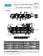
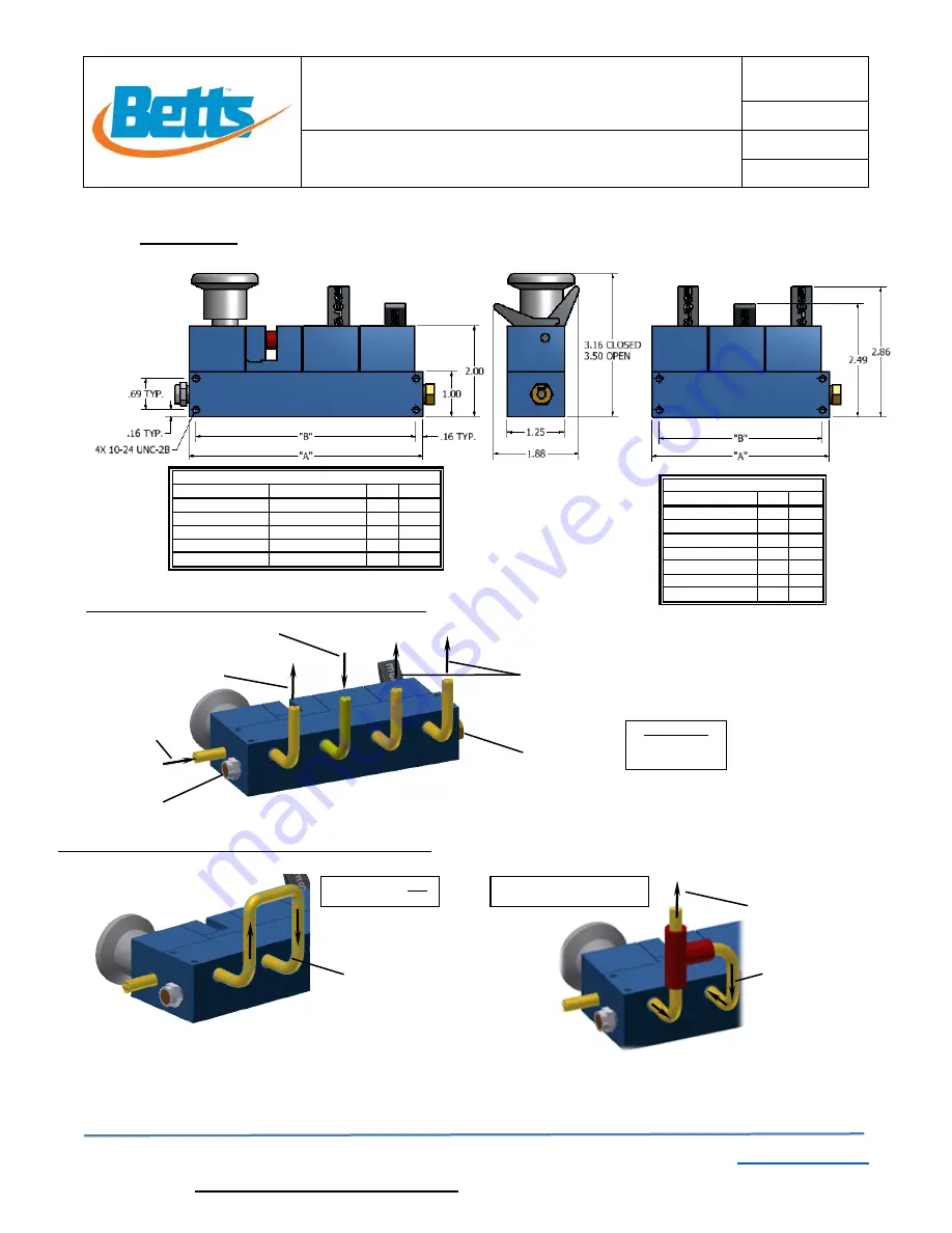


5.0 

Installation 


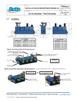
OUT TO NON-SEQUENTIAL 
VAPOR  VALVES 

JUMPER LINE  USED  TO 
BYPASS  AIR  TO TOGGLES 

PART  NUMBERS  

Pull and Hold 

Push/Pull 

“A” 

“B” 

AD14PH1ALFS 

AD14PP1ALFS 

3.91 

3.59 

AD14PH2ALFS 

AD14PP2ALFS 

5.16 

4.84 

AD14PH3ALFS 

AD14PP3ALFS 

6.41 

6.09 

AD14PH4ALFS 

AD14PP4ALFS 

7.66 

7.34 

AD14PH5ALFS 

AD14PP5ALFS 

8.91 

8.59 


Master Control Sequential  Plumbing

 Layout 

Master Control Non-Sequential  Plumbing Layout 

– 

(SAME  AS SEQUENTIAL  BUT WITH JUMPER LINE AS SHOWN BELOW)


NON-SEQUENTIAL  VAPOR 

VALVES  PLUMBED  INTO  SYSTEM 

PART  NUMBERS 

Toggles Only 

“A”  “B” 

AD14TO1ALFS 

1.41  1.09 

AD14TO2ALFS 

2.66  2.34 

AD14TO3ALFS 

3.91  3.59 

AD14TO4ALFS 

5.16  4.84 

AD14TO5ALFS 

6.41  6.09 

AD14TO6ALFS 

7.66  7.34 

AD14TO7ALFS 

8.91  8.59 


OR 

FITTING NOTE

ALL  FITTING  HOLES 

ARE  1/8-27  NPT 

VAPOR  VALVES  NOT 

PLUMBED  INTO SYSTEM 

JUMPER LINE  USED  TO 
BYPASS  AIR  TO TOGGLES 

 AIR  OUT FROM MASTER 

CONTROL TO  VAPOR  VALVES 

RETURN AIR FROM VAPOR  VALVES  TO 

PRESSURE  INDICATOR  SLIDE  AND FEED 

COMPARTMENT TOGGLES. 

AIR  SUPPLY  IN 

EXHAUST  PORT 

(DO NOT PLUG) 

AIR  OUT TO COMPARTMENT EMERGENCY 
VALVES  WHEN  TOGGLE  SELECTED 

FUSIBLE  PLUG   

Summary of Contents for Air Commander AD14PH1ALFS

Page 1: ...rm is considered uncontrolled 24 hrs after print date PART NUMBERS Including but not inclusive AD14PH1ALFS AD14PP1ALFS AD14TO1ALFS AD14PH2ALFS AD14PP2ALFS AD14TO2ALFS AD14PH3ALFS AD14PP3ALFS AD14TO3ALFS AD14PH4ALFS AD14PP4ALFS AD14TO4ALFS AD14PH5ALFS AD14PP5ALFS AD14TO5ALFS AD14TO6ALFS AD14TO7ALFS Table of Contents 1 0 General 2 0 Parts List 3 0 Description and Intended Use 4 0 Installation 5 0 In...

Page 2: ...orm maintenance on this equipment 1 5 As with any maintenance work proper safety gear and procedures must be used at all times A list of hazards may include but are not limited to contents under pressure loaded springs residual product flammable liquid and vapors pinch points 1 6 Safety alert symbols are used to alert operator to potential personal injury hazards These symbols are per ANSI Z535 5 ...

Page 3: ...28624AA 14 Wink Piston 1 Aluminum 75703AL 4 Manifold O ring Fluorosilicone 3926FS 15 Wink Spring Holder 1 Aluminum 75721AA 5 Manifold 1 Aluminum 75705AA XX 16 Exhaust Port 1 Nickel Steel Bronze 9Z4895 6 Hex Head Plug 1 Brass Teflon Tape 9V4852 Label Pull Hold AD75701 7 Toggle Wink Spring 1 Stainless 75698SL Label Push Pull AD75702 8 Fusible Plug 1 Brass w Solder FP15003BR 18 Cap Screw 6 32 x 3 4 1...

Page 4: ...icator slide that moves to red position when system is charged Toggles are used to activate desired compartment valves When loading or unloading is complete move all toggles to CLOSE positions and push master control to shut off air and exhaust entire system 4 2 2 Pull and Hold Master Control with Toggles Style AD14PH The Pull and Hold master control isolates the air supply to allow for more effec...

Page 5: ...P4ALFS 7 66 7 34 AD14PH5ALFS AD14PP5ALFS 8 91 8 59 Master Control Sequential Plumbing Layout Master Control Non Sequential Plumbing Layout SAME AS SEQUENTIAL BUT WITH JUMPER LINE AS SHOWN BELOW NON SEQUENTIAL VAPOR VALVES PLUMBED INTO SYSTEM PART NUMBERS Toggles Only A B AD14TO1ALFS 1 41 1 09 AD14TO2ALFS 2 66 2 34 AD14TO3ALFS 3 91 3 59 AD14TO4ALFS 5 16 4 84 AD14TO5ALFS 6 41 6 09 AD14TO6ALFS 7 66 7...

Page 6: ... 7 1 1 Disconnect from air supply and relieve all pressure prior to disassembly 7 1 2 Remove 2 cap screws 18 and drive pin 10 and set aside with toggle bat 19 If toggle piston 9 or toggle bat 9 are worn replace Be sure grooves in toggle piston 9 are clear of debris 7 1 3 Remove O ring 2 from toggle block 11 and replace 7 1 4 Remove O ring 2 from manifold 5 and manifold O ring 4 and replace 7 1 5 R...

Page 7: ...piston 14 in the red area reassemble and replace cap screws 18 and torque to approximately 10 16 in lbs 7 3 To repair rebuild master control 7 3 1 Disconnect from air supply and relieve all pressure prior to disassembly 7 3 2 Pull up on master control knob 1 and remove master control assembly 1 by unthreading from master control block 3 7 3 3 Remove O rings 2 from master control piston and replace...

Page 8: ...aster control assembly 1 Master control knob will not pull up Master control assembly 1 detent spring has damaged button holder See section 6 3 and replace master control assembly 1 System will not exhaust when toggle is switched to the CLOSED position Toggle is clogged or not operating correctly See section 6 1 and replace O rings 2 System will not exhaust when master control knob is in closed po...

Reviews: