14
3.4.4 Communication Error
In the event of a communication error,
‘Err’
is displayed. See
section 3.6 for more details should this occur.
3.5 RESOLVING A COMMUNICATION ERROR
In the event of a communication error, ‘Err’ is displayed on
the top right of the W.D.L. If this should happen, check that
the data cable is not damaged and is connected properly
and, that the assigned cabinet address parameters on the
Williams Easy Blast (W.E.B) (parameter “nr”) controller and
W.D.L (parameter “Cab.ADR”) are the same (see section
4.6.4).
3.6 BACKLIGHT AND DISPLAY
The backlight will remain on permanently (even when in
Standby mode). The contrast of the display can be adjusted
using the W.D.L’s parameters (see section 4.5.4 for more
details).
4.0 DISPLAY SCREENS AND BUTTON
OPERATION
4.1 SWITCHING ON THE W.D.L AND PRINTER
The data logger and printer will be switched on from Standby
mode automatically when the main controller is switched on
from Standby mode. For approximately 3 seconds after
switching on the cabinet, ‘- - -’ will be displayed, this indicates
a standard internal self-test phase before the controller is
ready for use.
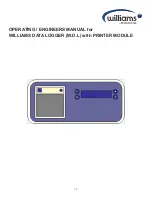
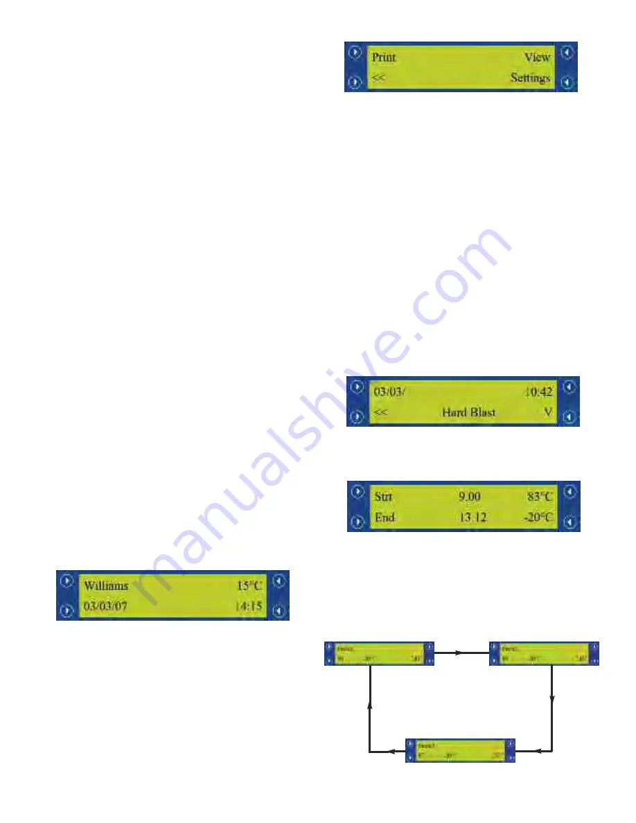
4.2 DEFAULT DISPLAY SCREEN
The default display screen will show the company name and
date on the left-hand side, the current cabinet status and time
are displayed on the right-hand side as shown in the diagram
directly below. The W.D.L will revert back to the default
display automatically after 30 seconds.
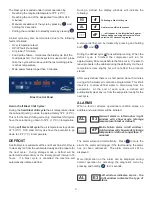
Access the Main Menu (refer to diagram below) by pressing
any button.
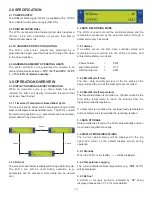
4.3 MAIN MENU SCREEN
The main menu screen allows you to select a number of
parameters and operations. See below for more details and
a diagram of the menu layout.
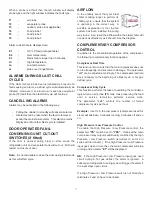
4.3.1 Printing Stored Data
The W.D.L retains approximately 7 days worth of data
(depending on usage) be default. This includes all blast
cycles that have been completed or cancelled, defrosts, store
cycles and all alarms. All of the stored data is printed by
pressing and holding the button next to
‘Print’
(1) for 3
seconds.
A confirmation message
‘Printing’
will be
displayed.
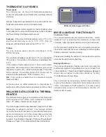
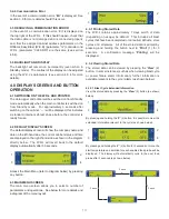
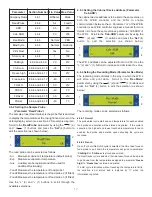
4.3.2 Viewing Stored Data
The stored data can be viewed by pressing the
‘View’
(2)
button. In some instances (such as when viewing blast cycle
or power failure alarm information) further information is
available relevant to the cycle / alarm (as shown below).
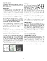
4.3.2.1 Blast Cycle Extended Information
View the stored data by pressing the
‘View’
(2) button (as shown
below).
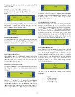
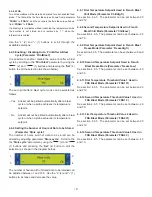
By pressing and holding the
‘V’
(4) button, it is possible to view the
extended information relevant to the cycle (as shown below).
By pressing and holding the
‘V’
(4) button for 3 seconds or more, the
start temperature and duration for each enabled food probe will be
displayed. The display will automatically cycle to the next food
probe after 3 seconds (as shown below).
3 secs
3 secs
3 secs
1
2
3
4
1
2
3
4
1
2
3
4
1
2
3
4
Summary of Contents for Williams WBC110
Page 12: ...12 by OPERATING ENGINEERS MANUAL for WILLIAMS DATA LOGGER W D L with PRINTER MODULE...
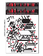
Page 20: ...20 PARTS LIST FOR A WBC35...
Page 21: ...21 PARTS LIST FOR A WBC60...
Page 22: ...22 PARTS LIST FOR A WBC75...
Page 23: ...23 PARTS LIST FOR A WBC110...
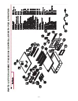
Page 24: ...24 PARTS LIST FOR A WMBC175 220 350 CONTROLLER WITH POD PRINTER...
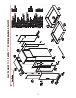
Page 25: ...25 PARTS LIST FOR A WMBC175 220 350 PANEL LAYOUT...
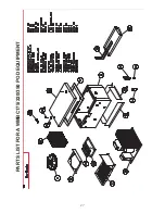
Page 26: ...26 PARTS LIST FOR A WMBC175 220 350 EQUIPMENT...
Page 27: ...27 PARTS LIST FOR A WMBC175 220 350 POD EQUIPMENT...
Page 28: ...28 PARTS LIST FOR A WMBC175 220 350 PANEL LAYOUT...
Page 29: ...29 PARTS LIST FOR A WMBC350 EQUIPMENT...
Page 30: ...30 PARTS LIST FOR A WMBC480 660 PANEL LAYOUT...
Page 31: ...31 PARTS LIST FOR A WMBC480 660 CONTROL PANEL WITH PRINTER POD...
Page 32: ...32 PARTS LIST FOR A WMBC480 EQUIPMENT LAYOUT...
Page 33: ...33 PARTS LIST FOR A WMBC660 EQUIPMENT LAYOUT...
Page 34: ...34 PARTS LIST FOR A WMBC480 660 POD EQUIPMENT...
Page 35: ...35 PARTS LIST FOR A WMBC480 660 PANEL LAYOUT...
Page 49: ...49...
Page 50: ...50...
Page 51: ...51...


