47
SET - 0154
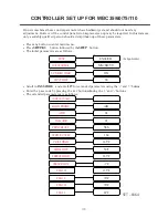
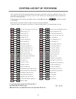
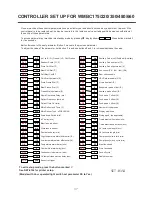
On new machines these control parameters have been factory set and should not need any adjustment. However if the
control panel is to be replaced, set-up may be required. In this instance, only a suitably qualified person should attempt
the set-up of these parameters.
To access parameter put machine into standby mode by pressing
O
, display shows
- - -
- - -
. Press button marked
3
for five seconds.
Button
2
moves to the next parameter. Button
3
moves to the previous parameter.
To adjust the value of the parameter, hold button
1
in and use buttons
2
and
3
to increase/decrease the value.
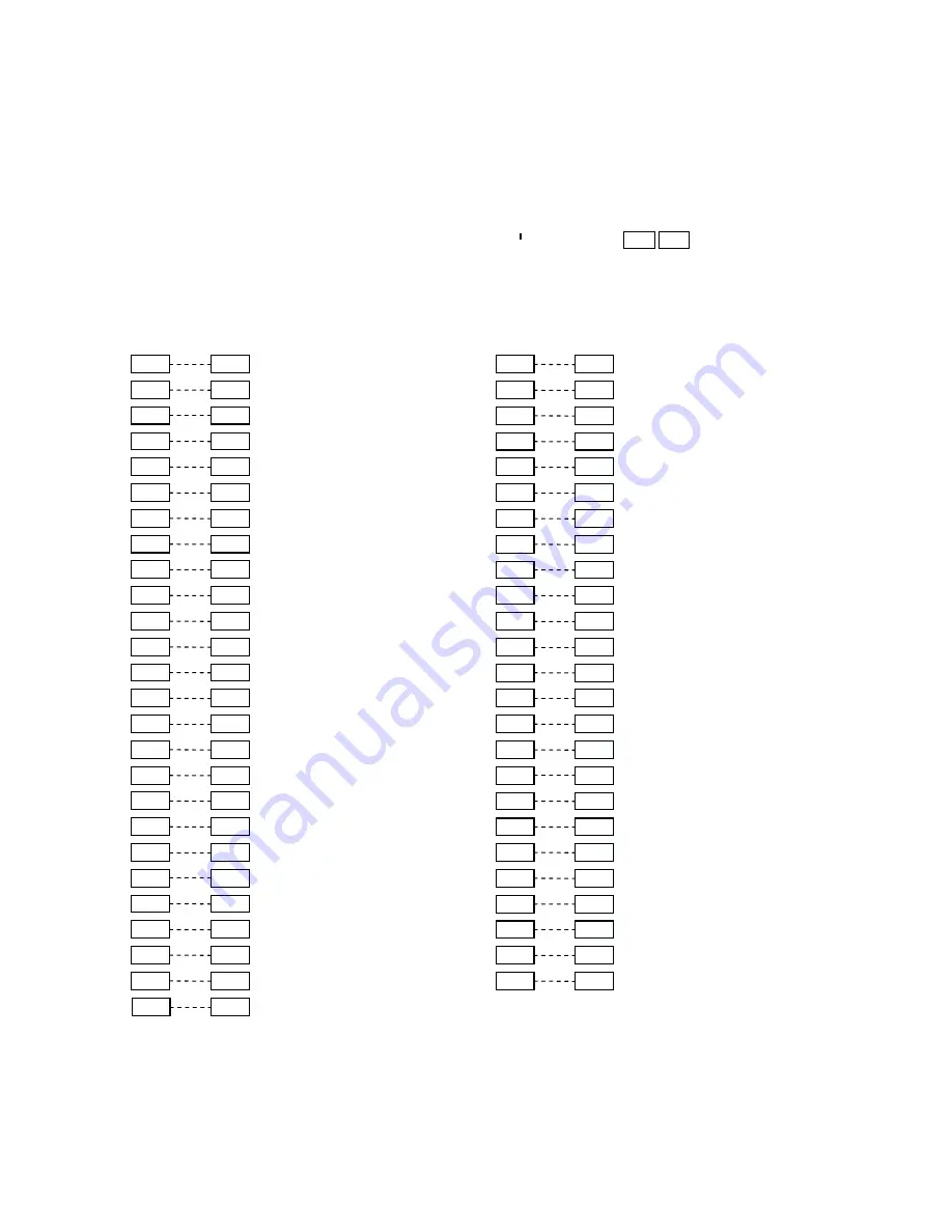
tyP
(ch) chill / (Fr) Freeze / (c-F) Chill-Freeze
c-F
3PM
Auxiliary Probe (no)/(Pod)defr./(Au)xiliary
no
ScL
Readout Scale (°C / °F)
°F
3SP
Auxiliary Probe set point (°F)
32
chS
Store Chill Stat (°F)
37
3hy
Auxiliary Probe Hysteresis (ºK)
-4
chb
Blast Chill Stat (°F)
12
Ac
Aux.control (Pr) / (AL) / (do) / (Sd)
AL
cbS
Soft Blast Chill
T
-4
dS
Door switch enable
no
chh
Chill Stat Hysteresis (°K)
2
PS
HP-LP alarm enable (Y/N)
no
FrS
Store Freeze Stat (°F)
-11
oS1
Air probe offset (ºK)
1
Frb
Blast Freeze Stat (°F)
-14
oS2
Evaporator probe offset (ºK)
0
Frh
Freeze Stat Hysteresis (°K)
3
oS3
Auxiliary probe offset (ºK)
0
rcd
Rapid Cool-down Delay (min)
0
oS4
Food probe 1 offset (ºK)
0
dFr
Defrost Frequency (per day)
4
oS5
Food probe 2 offset (ºK)
0
dto
Defrost Time Out (min)
20
oS6
Food probe 3 offset (ºK)
0
dLi
Main Defrost end Temp (°F)
39
nFP
Number of food probes
3
dty
Main Defrost Type : oFF/ELE/GAS
ELE
SiM
Display slow down
3
drn
Drain down Period (min)
2
Pod
Storage pod (as applicable)
y/n
ddy
‘dF’ delay (min)
5
bt1
Timed blast chill duration (min)
90
dFb
Blast fans in defrost
no
bt2
Timed blast freeze duration (min)
240
dFS
Store fans in defrost
no
uLt
UV lamp cycle length (min)
5
dFd
Restart fan delay (min)
2
uLF
UV fan cycle length (min)
2
Ath
High temperature alarm differential (ºK)
18
crt
Compressor(s) rest time (min)
5
AtL
Low temperature alarm differential (ºK)
-14
cdc
Compressor(s) duty cycle (min)
5
Atd
Temperature alarm delay (min)
60
FSb
Blast fan speed
20
Ado
Door switch alarm delay (min)
5
FSS
Store fan speed
20
Acc
Condenser clean interval (wks)
9
Foc
Fans off cycle
2
AuL
UV lamp strike detection delay (sec)
30
nr
Cabinet number
1
ArE
Buzzer re-trigger
yES
To exit set-up mode, press the button marked
X
See SET-0164 for printer setup.
(Models with door operated light switch set parameter DS to Yes)
CONTROLLER SET UP FOR WMBC175/220/350/480/660
Summary of Contents for Williams WBC110
Page 12: ...12 by OPERATING ENGINEERS MANUAL for WILLIAMS DATA LOGGER W D L with PRINTER MODULE...
Page 20: ...20 PARTS LIST FOR A WBC35...
Page 21: ...21 PARTS LIST FOR A WBC60...
Page 22: ...22 PARTS LIST FOR A WBC75...
Page 23: ...23 PARTS LIST FOR A WBC110...
Page 24: ...24 PARTS LIST FOR A WMBC175 220 350 CONTROLLER WITH POD PRINTER...
Page 25: ...25 PARTS LIST FOR A WMBC175 220 350 PANEL LAYOUT...
Page 26: ...26 PARTS LIST FOR A WMBC175 220 350 EQUIPMENT...
Page 27: ...27 PARTS LIST FOR A WMBC175 220 350 POD EQUIPMENT...
Page 28: ...28 PARTS LIST FOR A WMBC175 220 350 PANEL LAYOUT...
Page 29: ...29 PARTS LIST FOR A WMBC350 EQUIPMENT...
Page 30: ...30 PARTS LIST FOR A WMBC480 660 PANEL LAYOUT...
Page 31: ...31 PARTS LIST FOR A WMBC480 660 CONTROL PANEL WITH PRINTER POD...
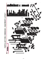
Page 32: ...32 PARTS LIST FOR A WMBC480 EQUIPMENT LAYOUT...
Page 33: ...33 PARTS LIST FOR A WMBC660 EQUIPMENT LAYOUT...
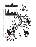
Page 34: ...34 PARTS LIST FOR A WMBC480 660 POD EQUIPMENT...
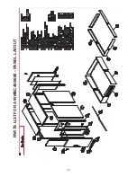
Page 35: ...35 PARTS LIST FOR A WMBC480 660 PANEL LAYOUT...
Page 49: ...49...
Page 50: ...50...
Page 51: ...51...

