6
The blast cycle is ended under normal operation by:
-
Reaching the required temperature 37°F (+3°C).
-
Reaching the end of the designated time (90 or 240
minutes).
-
Manual cancellation of the cycle by pressing
and
holding for 2 seconds.
-
Putting the controller into standby mode by pressing
A blast cycle may also be terminated due to the following
faults or failures:
-
Over temperature fault.
-
HP/LP fault (if enabled).
-
Air probe (T1) failure.
-
Food probe failure - terminates the blast cycle if all the
food probes fail. If a 3 probe system is used, and 1 probe
fails, the cycle will continue until the last working probe
reaches temperature.
-
Main power failure longer than 3 minutes.
Hard or Soft Blast Chill Cycles:
During the
hard blast chill cycle
the air temperature inside
the cabinet should go down to approximately 14°F (-10°C).
This is for the timed chilling cycle only. Hard blast chill cycles
have the potential to go down to 14°F (-10°C) in temperature.
During
soft blast chill cycle
the air temperature stays above
32°F (0°C). Soft blast chill cycles have the potential to go
down to 34°F (1°C) in temperature.
DEFROST
A defrost cycle is automatic at the end of each blast chill cycle
to clear any ice from the evaporator ready and to prepare for
the next cycle.
During storage mode a defrost will be
performed automatically at the factory preset interval of 6
hours.
If a blast cycle is cancelled the machine will
automatically initiate a defrost.
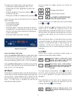
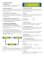
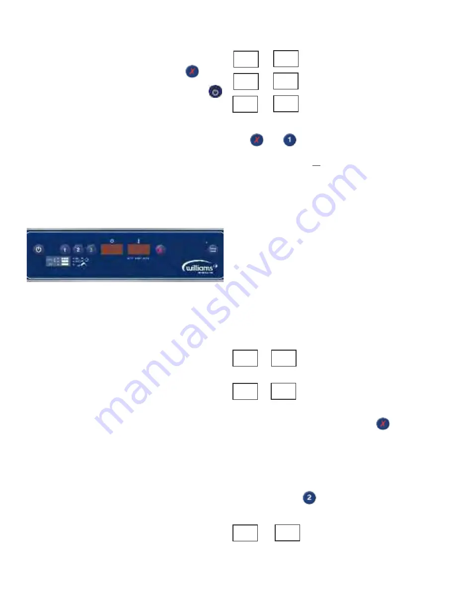
Blast Control Panel
During a defrost the display windows will indicate the
following:
Following a blast chill cycle
An alarm condition is present
- - - will appear in the left window if power
failure happens during defrost mode for a
duration of 3 minutes or greater
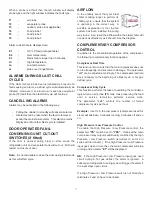
A manual defrost can be initiated by pressing and holding
both
and
During the defrost cycle
all
fans will stop running. When the
defrost cycle is finished the compressor will run for
approximately 60 seconds before the fans cut in. It is safe to
leave products in the cabinet during the defrost cycle; the air
temperature rises slightly but will not affect the products
stored.
After every defrost there is a short period; about 5 minutes
during which a blast cycle cannot be programmed. This short
interval is to allow defrost water to drain away from the
evaporator.
At the end of each cycle, a defrost will
automatically clear any ice from the evaporator ready for the
next cycle.
ALARMS
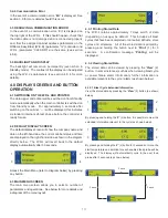
When a fault or adverse operational condition arises, an
audible and visual alarm will be initiated:
General alarm in left window / right
window will show mode (storage
temperature / blast or defrost)
Mains failure alarm in left window /
right window will show mode (storage
temperature / defrost; longer than 3
minutes)
The alarm will sound intermittently. Press
to mute the
alarm, the alarm will retrigger if the fault causing the alarm
has not been addressed.
The alarm mode will still be
displayed.
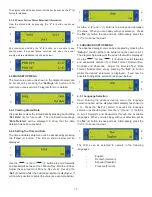
More information on the alarm can be displayed during
normal operation by accessing the diagnostic menu by
pressing and holding
for 3 seconds.
Left window indicates alarm - the
right window indicates the type of
alarm.
90
dF
AL
dF
- - -
dF
AL
03
- - -
dF
AL
E3
Summary of Contents for Williams WBC110
Page 12: ...12 by OPERATING ENGINEERS MANUAL for WILLIAMS DATA LOGGER W D L with PRINTER MODULE...
Page 20: ...20 PARTS LIST FOR A WBC35...
Page 21: ...21 PARTS LIST FOR A WBC60...
Page 22: ...22 PARTS LIST FOR A WBC75...
Page 23: ...23 PARTS LIST FOR A WBC110...
Page 24: ...24 PARTS LIST FOR A WMBC175 220 350 CONTROLLER WITH POD PRINTER...
Page 25: ...25 PARTS LIST FOR A WMBC175 220 350 PANEL LAYOUT...
Page 26: ...26 PARTS LIST FOR A WMBC175 220 350 EQUIPMENT...
Page 27: ...27 PARTS LIST FOR A WMBC175 220 350 POD EQUIPMENT...
Page 28: ...28 PARTS LIST FOR A WMBC175 220 350 PANEL LAYOUT...
Page 29: ...29 PARTS LIST FOR A WMBC350 EQUIPMENT...
Page 30: ...30 PARTS LIST FOR A WMBC480 660 PANEL LAYOUT...
Page 31: ...31 PARTS LIST FOR A WMBC480 660 CONTROL PANEL WITH PRINTER POD...
Page 32: ...32 PARTS LIST FOR A WMBC480 EQUIPMENT LAYOUT...
Page 33: ...33 PARTS LIST FOR A WMBC660 EQUIPMENT LAYOUT...
Page 34: ...34 PARTS LIST FOR A WMBC480 660 POD EQUIPMENT...
Page 35: ...35 PARTS LIST FOR A WMBC480 660 PANEL LAYOUT...
Page 49: ...49...
Page 50: ...50...
Page 51: ...51...


