Transport, installation and connection
4-12
4.7.3
Electrical connection for Ex-housings (ATEX Zone 1)
Danger to life caused by electrical current !
The safety instructions and local safety regulations
have to be observed during connection !
For connection data, please refer to the chapter ti-
tled "Technical data" as well as to the following ter-
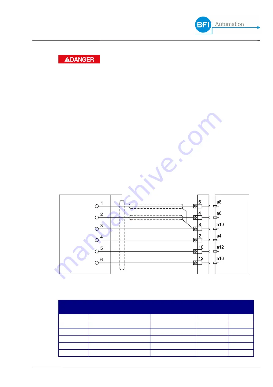
minal diagram.
Ensure that the available supply voltage complies
with the voltage indicated on the type plate.
Prior to connection, check the device and the con-
necting cables for visible damage.
Terminal diagram
Flame
BFI special cable
back
flame
scanner
type KW5
panel
amplifier
Terminal
block
Function
Colour of
conduct
Back panel
contact
3001
contact
1
Flame signal
WH
6
a8
2
Shutter puls
BN
4
a6
3
Signal GND
PK
8
a10
4
Power 24 VDC
GN
2
a4
5
Power supply GND
YE
10
a12
6
Reserve
GY
12
a16
Summary of Contents for 2.0L
Page 2: ...ii...
Page 20: ...Safety 2 8...
Page 40: ...Description 5 2...
Page 42: ...Operation of the flame scanner 6 2...
Page 44: ...Maintenance and servicing 7 2...
Page 46: ...Failures 8 2...
Page 48: ...Order data 9 2...
Page 50: ...Accessories 10 2...
Page 51: ...Accessories 10 3...


