Description
5-2
5.2
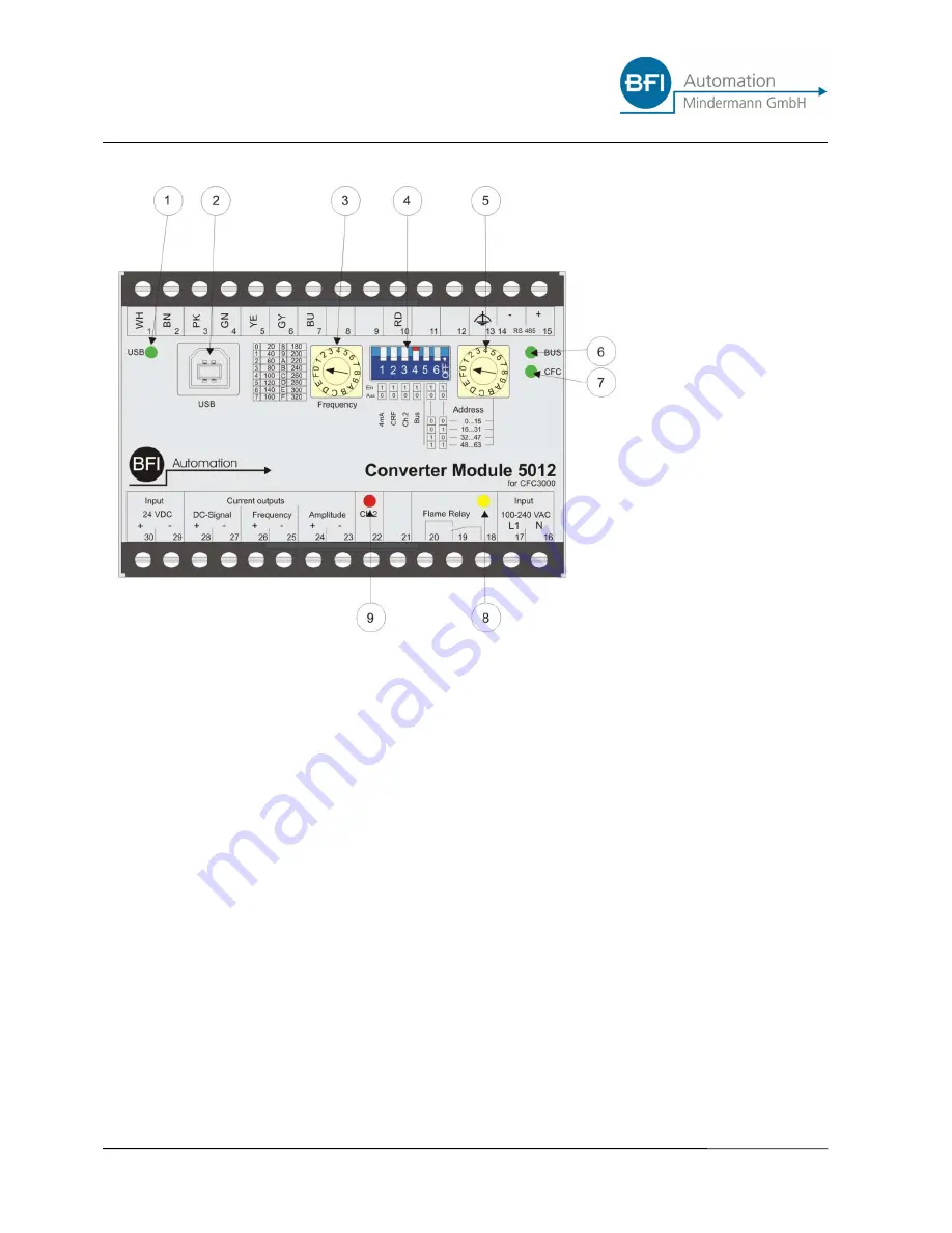
Controls and displays
1. Status LED - USB
2. USB connector
3. Selector for frequency range (mA out frequency)
4. DIP-switch
4.1.
Selection 0…20mA or 4…20mA
4.2.
Selection CRF (
C
urrent-
R
elay-
F
unction)
4.3.
Manual Selection of parameter set 2
4.4.
Selection BUS-termination
4.5.
Selection BUS-address range
4.6.
Selection BUS-address range
5. Selection BUS-Address
6. Status LED – BUS connected
7. Status LED – CFC connected
8. Status LED - Flame relay „ON“
9. Status LED - Channel 2 active
Summary of Contents for 5012
Page 2: ......
Page 11: ...General aspects 1 7 1 8 Declaration of conformity ...
Page 20: ...Safety 2 8 ...
Page 24: ...Technical data 3 4 ...
Page 26: ......
Page 30: ...Transport Installation and Connection 4 4 4 6 2 Network Configuration ...
Page 40: ...Description 5 8 ...
Page 42: ...Commisioning 6 2 ...
Page 44: ...Care and Maintenance 7 2 ...
Page 46: ...Failures 8 2 ...


