BFM® GLOBAL LTD.
|
EMAIL: sales@BFMfitting.com
|
WEB: BFMfitting.com
|
GUIDELINE
For
Oscil Offset
, the measurement to enter into the ‘Movement’ box is the
maximum horizontal difference in
either direction
from a fixed point on the top Spigot compared to the same point on the bottom Spigot. This includes any
initial offset (ie. you need to know the
total maximum horizontal difference in either direction vs if the two spigots were in
alignment
).
V 1 JAN 2017
PAGE 2 OF 2
GUIDELINES - IG CALCULATOR USER GUIDE
BFM
®
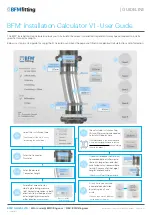
Installation Gap Calculator V1 - User Guide (continued)
For
Offset Static
, the measurement to enter into the ‘Offset’ box is the horizontal difference between a fixed point on the top
Spigot compared to the same point on the bottom Spigot.
For
Vibratory
or
Oscillating
, the measurement to enter into the ‘Movement’ box is the
maximum horizontal movement in either
direction
from a fixed point on the top Spigot compared to the same point on the bottom Spigot.
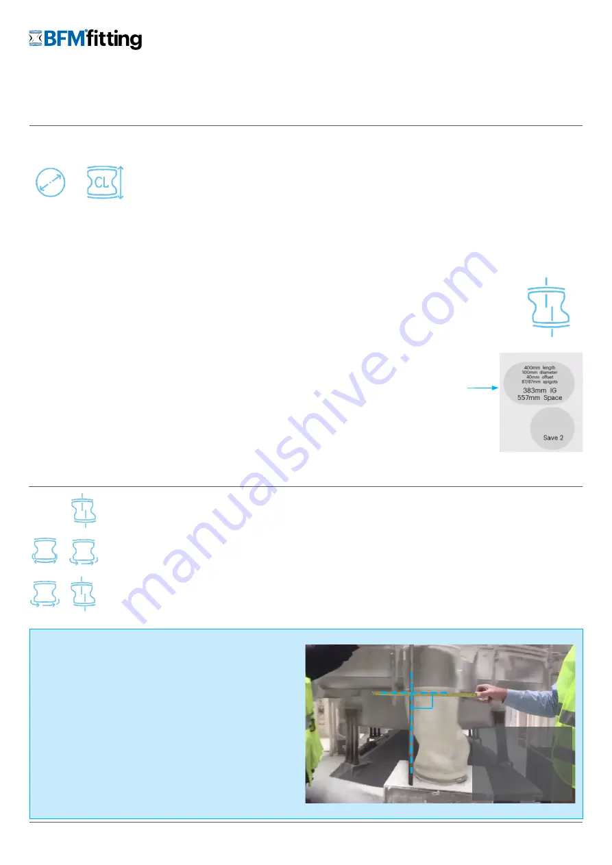
The best way to measure Movement is to have a vertical marker (a
stick or pole) held up at the edge of the pipe and then hold a tape
measure at right-angles to the pole so that it extends across the front
and past the edge of the moving spigot.
Then, using slow-motion on your phone/camera, video the
movement of the spigot. You must have the camera at the same
height and at a 900 angle to the tape measure to get an accurate
reading.
It is best to video the movement at both start up and wind down, as
there is often a larger swing at this time than during regular operation.
We recommend watching the
‘Measuring for the Right Connector’
video on the BFM
®
fitting website for more guidance.
Measuring Offset & Movement
HOW TO MEASURE:
Static:
Maximum Offset = 20% of CL (Connector Length) up to 100mm (max)
Vibratory:
Maximum Movement = 20% of CL (Connector Length) up to 100mm (max)
Oscillating:
Maximum Movement = 20% of CL (Connector Length) up to 100mm (max)
and
Minimum IG (Installation Gap) is (CL-25%)
MAXIMUM OFFSET/
MOVEMENT:
The largest connector diameter is 1,650mm (65”), and the corresponding lengths are subject to the following:
•
Any connector from 700mm (271/2”) to 1,000mm (391/2”) diameter can have a maximum length of 500mm (20”).
•
Any connector from 1,050mm (41”) diameter to 1,650mm (65”) can have a maximum length of 200mm (8”).
NB: There are additional diameter/length restrictions that apply to different materials and for connectors with rings - the calculations are
provided based on our most common Seeflex 040E material. Refer to the ‘
’ for more information on the
other material restrictions that apply.
DIAMETER VS LENGTH:
The top and bottom spigots can have different lengths. The default for both is set at the standard length of 87 mm (31/2”),
but they can be cut down to 35mm (13/8”) length minimum. For any spigot length under 50mm (2”), it is important to
ensure there is a heat sink to avoid distorting spigot when welding onto the pipe.
SPIGOT LENGTH:
To complete the calculation, ensure you have pressed ‘Enter’ on your keyboard to make
sure your last data entry has been accepted. You can then click on the ‘Save 1’ circle on
the right hand side of the Calculator screen - this will save all of the measurements for that
particular calculation. You can continue with more calculations and save up to 5 on screen
at the same time.
To save these calculations for future reference, you will need to take screen-shots (either
using a ‘clipping’ tool or the ‘print-screen’ function).
SAVING YOUR
CALCULATIONS:
900
To get an accurate
measurement, ensure
video is taken at a direct
front-on view of the
movement and at the
same height as the tape
measure.
OR
+
(TIP: it is usually easier to measure at the outside edge of the spigots)


