background image

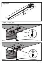
39-41 mm

1

15

6,3

6

5

2

3

4

10 mm

V1

V1

V1

10 mm

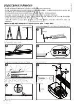
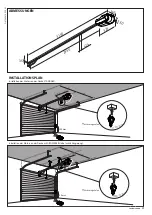
Ouvrir l'emballage et couper le collier.  

Placer le rail en le développant dans le sens de la flèche. 

ATTENTION: composer le rail

correctement

EN EVITANT LES EVENTUELS DENIVELES

Fixer le rail sur la base

Déplacer le connecteur su milieu des deux premiers

rails et soulever les ailettes comme le montre la figure.

Répéter l'opération avec le deuxième connecteur.

Serrer l'écrou avec la douille Ø 10 mm et régler de la façon indiquée au point 5.

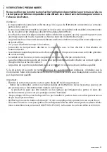
SECURITE PENDANT L'INSTALLATION

Pendant l'utilisation, nous recommandons :

-  d'utiliser les outils appropriés, comme spécifié dans ces instructions.

-  d'utiliser des équipements de protection individuelle adaptés (lunettes de protection, gants) aux 

opérations que vous êtes en train d'effectuer.

-  de signaler les travaux en cours et ne pas laisser le chantier sans surveillance.

-  de ne pas brancher le réseau d'alimentation avant d'avoir terminé le montage.

- après avoir relié l'appareil au réseau,  de ne toucher que les boutons et les moyens de réglage 

nécessaires à la programmation de la centrale.

- toute intervention ou réparation qui n'est pas spécifiée dans les présentes instructions n'est pas 

autorisée.

OPERATIONS PRELIMINAIRES ET FIXATION DU RAIL SUR LA BASE  

44

  -  

FAUNUS 600 KIT

D812456 10550_02

Summary of Contents for FAUNUS 600 KIT

Page 1: ...Attention Veuillez lire attentivement les Avertissements qui se trouvent l int rieur Achtung Bitte lesen Sie aufmerksam die Hinweise im Inneren D812456 10550_02 23 07 15 AUTOMAZIONI PER PORTE SEZIONA...
Page 2: ...LAGGIO BRACCIO TRAINO 10 MONTAGGIO STAFFA ANCORAGGIO SU SEZIONALE 10 ASSEMBLAGGIO STAFFA ANCORAGGIO CON BRACCIO TRAINO 10 FISSAGGIO STAFFE SAS1 SAS2 per soffitto con altezza SUPERIORE 11 COLLEGAMENTO...

Page 3: ...aretuttiidispositividisicurezza fotocellule costesensibili ecc necessariaproteggerel areadapericoli diimpatto schiacciamento convogliamento cesoiamento Tenereinconsiderazionelenormativeeledirettive in...

Page 4: ...IGLIA 1 1 STAFFA PORTA BINARIO 1 SUPPORTO BINARIO 2 STAFFA A OMEGA 3 BINARIO IN TRE PARTI 3 2 RONDELLA 8 4 17 1 6 18 TASSELLO TIPO FISHER S10 6 VITE LEGNO M8X40 4 8 ZN 6 VITE CON QUADRO SOTTOTESTA M6X...

Page 5: ...INE 3x 1 5 mm 2 LINE 3x 1 5 mm 2 DIMENSIONI SCHEMA D INSTALLAZIONE Non in dotazione Non in dotazione Installazione motore su soffitto STANDARD Installazione motore su soffitto con altezza SUPERIORE co...

Page 6: ...E14 Temperatura di funzionamento 20 C 60 C Grado di protezione IPX0 Peso testa motore 5 kg Rumorosit 70dB A Dimensioni Vedi DIMENSIONI Max dimensioni porta 10m2 Alimentazione accessori 24V 180 mA 24V...

Page 7: ...rrettamente la parte inferiore della porta deve essere dotata di un profilo deformabile al fine di evitare un contatto rigido e aumentare la superficie di contatto le parti della porta non debordino s...

Page 8: ...nte l installazione si raccomanda di utilizzare gli utensili appropriati come specificato da queste istruzioni utilizzare dispositivi di protezione individuale adeguati occhiali protettivi guanti alle...

Page 9: ...il centro del sezionale e le misure indicate nel cerchio Fissare la staffa porta binario come indicato in sequenza Dopo aver installato la staffa porta binario su muro fissare il binario ad essa come...

Page 10: ...R1 F1 V1 R4 8 18 10 F1 40 8 V1 FISSAGGIO BINARIO AL SOFFITTO 1 Fissare il binario a soffitto come da figura MONTAGGIO STAFFA ANCORAGGIO SU SEZIONALE ASSEMBLAGGIO STAFFA ANCORAGGIO CON BRACCIO TRAINO...

Page 11: ...SSAGGIO STAFFE SAS1 SAS2 per soffitto con altezza SUPERIORE Staffe non in dotazione le viti le rondelle e i dadi necessari ad assemblare le staffe sono all interno del KIT STAFFE le viti i tasselli e...

Page 12: ...llaretedialimentazione visiauninterruttoredifferenzialeconsoglianonsuperiore a 0 03A e a quanto previsto dalle norme vigenti Verificare che l impianto di terra sia realizzato correttamente collegare a...

Page 13: ...N UP 4 T1 RADIO OK DOWN UP 3 T1 RADIO OK DOWN UP T1 T1 T1 T1 T1 RADIO RADIO RADIO RADIO RADIO SET SET SET OK OK OK OK DOWN DOWN UP UP DOWN DOWN UP DOWN UP UP SET SET SET SET AUTOSET Attenzione durante...

Page 14: ...UP RADIO SET DOWN UP OK RADIO SET DOWN UP OK RADIO SET DOWN UP OK OK RADIO SET DOWN UP RADIO SET DOWN UP OK RADIO SET DOWN UP OK OK ELIMINAZIONE TELECOMANDI non in dotazione non in dotazione MEMORIZZ...

Page 15: ...LAMPADA DI CORTESIA DESCRIZIONE NOTE Tempodiaccen sionedall ultima manovra 90s Segnalazione termica 3lampeggiadinizio manovra Attendereilraffreddamen to dell automazione Segnalazionemal funzionamento...

Page 16: ...comando applicati Verificare l integrit delle connessioni elettriche e dei cablaggi in particolare lo stato delle guaine isolanti e dei pressa cavi Durante la manutenzione eseguire la pulizia delle o...

Page 17: ...na diminuzione della portata della trasmittente pu essere dovutaallebatteriechesistanno scaricando Quando il led della trasmittente lampeggia indica che le batterie sono scariche e devono essere sosti...

Page 18: ...sblocco manuale potrebbe causare movimenti incontrollati della porta se in presenza di guasti meccanici o di condizioni di squilibrio La rottura o l usura di organi meccanici della porta parte guidat...

Page 19: ...MANUTENZIONE Ubicazione Motore azionamento Proprietario Fotocellule Dimensioni e peso Radiocomando Materiale PVC alluminio Lampeggiante Data di installazione Altro Data Descrizione dell intervento No...

Page 20: ...THE TRACK TO THE CEILING 28 TOWING ARM ASSEMBLY 28 ASSEMBLY OF ANCHORING BRACKET ON THE SECTIONAL DOOR 28 ASSEMBLY OF ANCHORING BRACKET WITH TOWING ARM 28 FASTENING SAS1 SAS2 BRACKETS for HIGHER ceili...

Page 21: ...ply all safety devices photocells safety edges etc required to keep the area free of impact crushing dragging and shearing hazards Bear in mind the standards and directives in force Good Practice crit...

Page 22: ...N 1 1 TRACK HOLDING BRACKET 1 TRACK SUPPORT 2 OMEGA BRACKET 3 TRACK IN THREE PARTS 3 2 WASHER 8 4 17 1 6 18 FISHER TYPE S10 DOWEL 6 40xM8 4 8 ZN WOODEN SCREW 6 80xM6 ROUND HEAD SQUARE NECK BOLTS 1 TOO...

Page 23: ...00 mm 200 mm LINE 3x 1 5 mm 2 LINE 3x 1 5 mm 2 DIMENSIONS INSTALLATION DIAGRAM Not provided Not provided Motor installation on STANDARD ceiling Motor installation on HIGHER ceiling with extension FAUN...

Page 24: ...24V bulb 25W max E14 Operating temperature 20 C 60 C Protection rating IPX0 Motor head weight 5 kg Noise level 70dB A Dimensions See DIMENSIONS Max door dimensions 10m2 Auxiliary power supply 24V 180...

Page 25: ...the leaf is in good condition well balanced and opens and closes correctly the lower part of the door must be fitted with a deformable profile in order to avoid a rigid contact and increase the contac...

Page 26: ...nstructed in point 5 SAFETY DURING INSTALLATION During installation please use appropriate tools as specified by these instructions use personal protection equipment protective goggles gloves when wor...

Page 27: ...entre of the sectional door and the measurements shown in the circle Fix the track holding bracket as shown in the sequence After installing the track holding bracket onto the wall fix the track to th...

Page 28: ...V1 R4 8 18 10 F1 40 8 V1 FASTENING THE TRACK TO THE CEILING 1 Fasten the track to the ceiling as shown in the figure ASSEMBLY OF ANCHORING BRACKET ON THE SECTIONAL DOOR ASSEMBLY OF ANCHORING BRACKET W...

Page 29: ...18 10 F 40 8 V3 FASTENING SAS1 SAS2 BRACKETS for HIGHER ceiling Brackets not supplied the screws washers and nuts necessary to assemble the brackets are inside the BRACKET KIT the screws dowels and wa...

Page 30: ...r supply there is a residual current circuit breaker that trips at no more than 0 03A as well as any other equipment required by code Make sure the earth system has been correctly installed earth all...

Page 31: ...P 4 T1 RADIO OK DOWN UP 3 T1 RADIO OK DOWN UP T1 T1 T1 T1 T1 RADIO RADIO RADIO RADIO RADIO SET SET SET OK OK OK OK DOWN DOWN UP UP DOWN DOWN UP DOWN UP UP SET SET SET SET CLOSING OPENING AUTOSET WARNI...

Page 32: ...UP RADIO SET DOWN UP OK RADIO SET DOWN UP OK RADIO SET DOWN UP OK OK RADIO SET DOWN UP RADIO SET DOWN UP OK RADIO SET DOWN UP OK OK CANCELLING THE REMOTE CONTROLS not provided not provided SAVING THE...

Page 33: ...TION NOTES ON time starting from last operation 90s Thermal overload warning 3 flashes at start of operation Allow automated device to cool Microswitch malfunction warning 4 flashes at end of operatio...

Page 34: ...nd closing operations with the control devices applied Check that electrical connections and cabling are intact making extra sure that insulating sheaths and cable glands are undamaged While performin...

Page 35: ...REPLACEMENT MAINTENANCE A reduction in transmitter range may be due to the batteries dying WhenthetransmitterLED flashes itmeansthebatteriesare dead and must be replaced The battery terminals should...

Page 36: ...f there are mechanical faults or loss of balance The breakage or wear of any mechanical parts of the door operated part such as cables springs supports hinges guides maygenerateahazard Have the system...

Page 37: ...TENANCE REGISTER Position Motor operating Owner Photocells Weight and size Transmitter Material PVC aluminium Flashing light Installation date Other Date Description of the intervention Name and signa...

Page 38: ...RAINEMENT 46 MONTAGE ETRIER ANCRAGE SUR SECTIONNELLE 46 ASSEMBLAGE ETRIER ANCRAGE AVEC BRAS ENTRAINEMENT 46 FIXATION ETRIER SAS1 SAS2 POUR PLAFOND AVEC HAUTEUR SUPERIEURE 47 BRANCHEMENT SUR RESEAU ELE...

Page 39: ...curit photocellules linteaux sensibles etc n cessaires pour prot ger la zone contre les risques de choc d crasement d entra nement ou de cisaillement Tenir compte des r glements et des directives en...

Page 40: ...LE 1 1 ETRIER PORTE RAIL 1 SUPPORT RAIL 2 ETRIER EN OMEGA 3 RAIL EN TROIS PARTIES 3 2 RONDELLE 8 4 17 1 6 18 CHEVILLE TYPE FISCHER S10 6 VIS BOIS M8X40 4 8 ZN 6 VIS AVEC CARRE SOUS TETE M6X80 1 DOUILL...

Page 41: ...0 mm LINE 3x 1 5 mm 2 LINE 3x 1 5 mm 2 DIMENSIONS SCHEMA D INSTALLATION Pas fourni Pas fourni Installation moteur sur plafond STANDARD Installation moteur sur plafond avec hauteur SUPERIEURE avec rall...

Page 42: ...ampe 24V 25W max E14 Temp raturedefonctionnement 20 C 60 C Degr de protection IPX0 Poids t te moteur 5 kg Bruit 70dB A Dimensions Cf DIMENSIONS Dimensions maxi porte 10m2 Alimentation des accessoires...

Page 43: ...ouvre et se ferme correctement la partie inf rieure de la porte est munie d un profil d formable afin d viter un contact rigide et d augmenter la surface de contact les parties de la porte ne d borden...

Page 44: ...ation nous recommandons d utiliser les outils appropri s comme sp cifi dans ces instructions d utiliser des quipements de protection individuelle adapt s lunettes de protection gants aux op rations qu...

Page 45: ...centre de la sectionnelle et les mesures indiqu es dans le cercle Fixer l trier porte rail de la fa on indiqu e en s quence Apr s avoir install l trier porte rail au mur fixer le rail sur l trier de...

Page 46: ...R1 F1 V1 R4 8 18 10 F1 40 8 V1 FIXATION RAIL AU PLAFOND 1 Fixer le rail au plafond comme le montre la figure MONTAGE ETRIER ANCRAGE SUR SECTIONNELLE ASSEMBLAGE ETRIER ANCRAGE AVEC BRAS ENTRAINEMENT A...

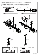
Page 47: ...ER SAS1 SAS2 pour plafond avec hauteur SUPERIEURE Etriers pas fournis les vis les rondelles et les crous n cessaires pour assembler les triers se trouvent l int rieur du KIT ETRIERS les vis les chevil...

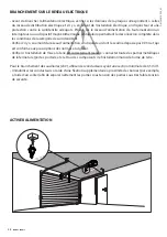
Page 48: ...du r seau d alimentation un disjoncteur dont le seuil ne d passe pas 0 03 A et qui est conforme aux prescriptions des normes en vigueur V rifier si l installation de mise la terre est correctement r a...

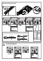
Page 49: ...RADIO OK DOWN UP T1 T1 T1 T1 T1 RADIO RADIO RADIO RADIO RADIO SET SET SET OK OK OK OK DOWN DOWN UP UP DOWN DOWN UP DOWN UP UP SET SET SET SET FERMETURE OUVERTURE AUTOCONFIGURATION Attention pendant l...

Page 50: ...OWN UP RADIO SET DOWN UP OK RADIO SET DOWN UP OK RADIO SET DOWN UP OK OK RADIO SET DOWN UP RADIO SET DOWN UP OK RADIO SET DOWN UP OK OK ELIMINATION DES T L COMMANDES pas fourni pas fourni MEMORISATION...

Page 51: ...DESCRIPTION REMARQUE Tempsd allumage partir de la der ni res man uvre 90s Signalisation thermique 3 clignotements en d butdeman uvre Attendre le refroidisse ment de l automatisation Signalisationmau v...

Page 52: ...rmeture avec les dispositifs de commande appliqu s V rifier l int grit des connexions lectriques et des c blages en particulier l tat des gaines isolantes et des presse c bles Pendant les op rations d...

Page 53: ...la port e de l metteur peut tre due aux batteries qui sont en train de se d charger Lorsque le voyant de l metteur clignote ceci indique quelesbatteriessontd charg es et qu elles doivent tre rempla c...

Page 54: ...ion du d verrouillage manuel risque de provoquer des mouvements incontr l s de la porte en pr sence de pannes m caniques ou de conditions de d s quilibre Laruptureoul usuredesorganesm caniquesdela por...

Page 55: ...TRETIEN Emplacement Moteur actionnement Propri taire Photocellules Dimensions et poids Radiocommande Mat riel PVC aluminium Clignotant Date d installation Autre Date Description de l intervention Nom...

Page 56: ...DECKE 64 MONTAGE DER ZUGARMS 64 MONTAGE DES VERANKERUNGSB GELS AM SEKTIONALTOR 64 MONTAGE DES VERANKERUNGSB GELS MIT ZUGARM 64 BEFESTIGUNG DER B GEL SAS1 SAS2 f r Decken mit GR SSERER H he 65 ANSCHLU...

Page 57: ...m EN 12978 und EN 12453 entsprechen WendenSiealleSicherheitsvorrichtungen Fotozellen Sensorenusw an diezumSchutzdesGefahrenbereiches gegen Aufprall Quetschung Erfassung und Abtrennung von Gliedma en e...

Page 58: ...T 1 1 SCHIENENB GEL 1 SCHIENENHALTERUNG 2 OMEGA B GEL 3 SCHIENE IN DREI TEILEN 3 2 SCHEIBE 8 4 17 1 6 18 FISCHER D BEL S10 6 HOLZSCHRAUBE M8X40 4 8 ZN 6 SCHRAUBE MIT UNTERKOPF VIERKANT M6X80 1 ZAHNBUC...

Page 59: ...x 1 5 mm 2 LINE 3x 1 5 mm 2 ABMESSUNGEN INSTALLATIONSPLAN Nicht mitgeliefert Nicht mitgeliefert Installation des Motors an der Decke STANDARD Installation der Motors an der Decke mit GR SSERER H he mi...

Page 60: ...E14 Betriebstemperatur 20 C 60 C Schutzgrad IPX0 Gewicht Motorkopf 5 kg Ger uschpegel 70 dB A Abmessungen Siehe ABMESSUNGEN Max Abmessungen T r 10 m2 Stromversorgung Zubeh r 24 V 180 mA 24 Vsafe 180 m...

Page 61: ...reinverformbaresProfilaufweist umeinenstarrenKontaktmitderKontaktfl che zu vermeiden dieBauteilederT rnichtandenB rgersteigodereine ffentlichzug nglicheStra enfl chegrenzen InstallierenSiedieMotorisi...

Page 62: ...5 angegeben ein SICHERHEIT W HREND DER INSTALLATION W hrend der Installation beachten geeignetes Werkzeug benutzen wie in den Anweisungen angegeben beidenArbeitengeeignetepers nlicheSchutzausr stung S...

Page 63: ...onaltors und der im Kreis angegebenen Abmessungen installiert werden Befestigen Sie den Schienenb gel wie in der Sequenz gezeigt Befestigen Sie die Schiene nach der Installation der Schienenb gels wie...

Page 64: ...4 8 18 10 F1 40 8 V1 BEFSTIGUNG DER SCHIENE AN DER DECKE 1 Befestigen Sie die Schiene an der Decke wie auf der Abbildung gezeigt MONTAGE DES VERANKERUNGSB GELS AM SEKTIONALTOR MONTAGE DES VERANKERUNGS...

Page 65: ...GEL SAS1 SAS2 f r Decken mit GR SSERER H he B gel nicht mitgeliefert die Schrauben die Scheiben und die Muttern die f r die Montage der B gel erforderlich sind sind im KIT B GEL enthalten die Schraube...

Page 66: ...g ein Differentialschalter mit einer Eingriffsschwelle von nicht mehr als 0 03 A vorgeschaltet ist der den geltenden Normen entspricht StellenSiesicher dassdieErdungsanlageordnungsgem ausgef hrtworden...

Page 67: ...N UP 3 T1 RADIO OK DOWN UP T1 T1 T1 T1 T1 RADIO RADIO RADIO RADIO RADIO SET SET SET OK OK OK OK DOWN DOWN UP UP DOWN DOWN UP DOWN UP UP SET SET SET SET AUTOSET Achtung W hrend des Autosets ist die Que...

Page 68: ...IO SET DOWN UP OK RADIO SET DOWN UP OK RADIO SET DOWN UP OK OK RADIO SET DOWN UP RADIO SET DOWN UP OK RADIO SET DOWN UP OK OK L SCHUNG VON FERNBEDIENUNGEN nicht mitgeliefert nicht mitgeliefert ABSPEIC...

Page 69: ...Funkprogrammierung 1 ZONENBE LEUCHTUNG BESCHREIBUNG ANMERKUNGEN Einschaltzeit nach dem letzten Ma n ver 90 Sekunden Anzeige Thermo schutzschalter 3MalBlinkenbeiBeginn des Man vers DieAbk hlungderAutom...

Page 70: ...schlossenen Steuervorrichtungen berpr fen Sie die elektrischen Anschl sse und die Verkabelung sowie insbesondere den Zustand der Isolierungen und der Kabeldurchf hrungen Nehmen Sie w hrend der Wartung...

Page 71: ...CHERUNG WARTUNG Falls die Reichweite des Senders nachl sst kanndiesdaranliegen dass die Batterien leer sind Das Aufblinken der LED des Senders zeigt an dass die Batterien leer sindundausgewechseltwerd...

Page 72: ...n um unbeabsichtigte Bet tigungen der Automati sierung zu vermeiden DieAktivierungdermanuellenEntsperrungk nnte bei mechanischen Defekten oder Ungleichgewi chtssituationen zu unkontrollierten Bewegung...

Page 73: ...ISTER Position Motor Antrieb Eigent mer Fotozellen AbmessungenundGewicht Fernbedienung Material PVC Aluminium Blinkleuchte Datum der Installation Sonstiges Datum Beschreibung des Eingriffes Name und U...

Page 74: ...74 FAUNUS 600 KIT D812456 10550_02...

Page 75: ...FAUNUS 600 KIT 75 D812456 10550_02...

Page 76: ...12 BENELUX BFT BENELUX SA 1400 Nivelles www bftbenelux be POLAND BFT POLSKA SP Z O O 05 091 Z BKI www bft pl CROATIA BFT ADRIA D O O 51218 Drazice Rijeka www bft hr PORTUGAL BFT SA COMERCIO DE AUTOMA...

Reviews: