background image

- 31 -

ES

ESPAÑOL

START

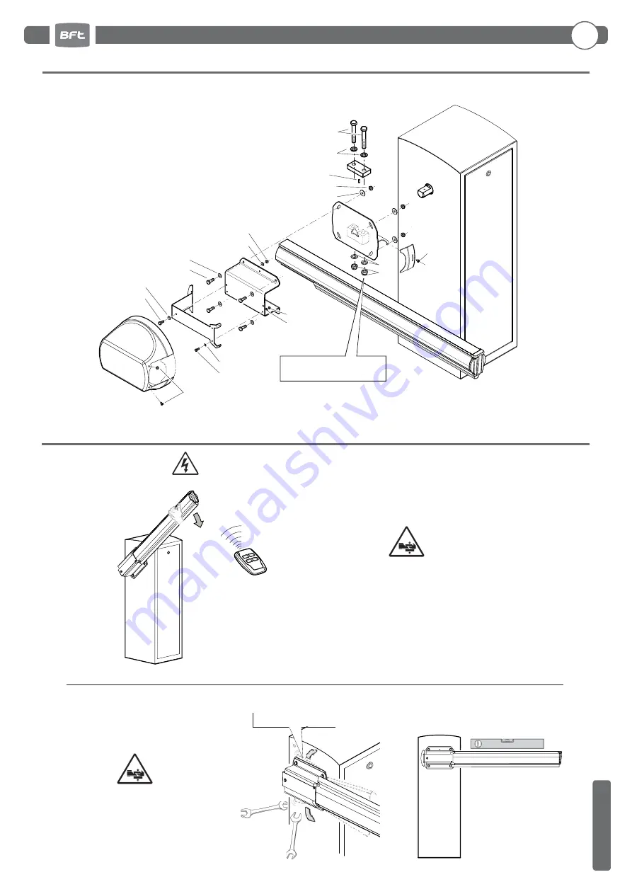
• Insertar un trozo de barra de aproximadamente 1 metro en el 

portabarra

• Dar el comando “START” para colocar el portabarra en posición 

horizontal

• Tirar de la barra hacia abajo para ayudar al reductor a vencer la 

fuerza del muelle calibrado de antemano

Instalar la barra y ajustar el portabarra

Portabarra regulable

2.5 ALINEAR LA BARRA

Conectar eléctricamente la centralita  (ver punto 2.8)

PARA ALINEAR LA BARRA CON LA CAL-

ZADA, ACTUAR SOBRE EL PORTABARRA 

REGULABLE. 

2 x 17mm

Compruebe que la barra esté

en posición horizontal

2.4 INSTALACIÓN DE LA  BARRA

M6x10

M6x10

M10x25

M8x20

M8

M6x16

M6x16

Ø10

Ø8

Ø8

Ø6

Ø6

Ø16

Ø16

Ø10

Ø6x16

M16x100

M16

M10

APRETAR 210Nm

2. Instalaciòn

Summary of Contents for Maxima Ultra 68

Page 1: ...le Avvertenze all interno Caution Read Warnings inside carefully Attention Veuillez lire attentivement les Avertissements qui se trouvent à l intérieur Achtung Bitte lesen Sie aufmerksam die Hinweise im Inneren Atención Leer atentamente las Advertencias en el interior Let op Lees de Waarschuwingen aan de binnenkant zorgvuldig BARRIERA AUTOMATICA AUTOMATIC BARRIER BARRIÈRE AUTOMATIQUE AUTOMATISCHE ...

Page 2: ......

Page 3: ...ion structure pag 17 2 3 Installation des springs pag 17 2 4 Installation de la lisse pag 19 2 5 Alignement de la lisse pag 19 2 6 Equilibrage de la lisse pag 20 2 7 Optionals pag 20 2 8 Branchements electriques pag 20 3 Utilisation et maintenance 3 1 Sécurité générale pag 21 3 2 Avertissements pag 21 3 3 Utilisation pag 21 3 4 Manoeuvre manuelle pag 21 3 5 Routine maintenance pag 21 1 Allgemeine ...

Page 4: ...ZZA GENERALE Smaltire i materiali di imballo plastica cartone polistirolo ecc secondo quanto previsto dalle norme vigenti Non lasciare buste di nylon e polistirolo a portata dei bambini Togliere l alimentazione elettrica prima di qualsiasi intervento sull impianto Scollegare anche eventuali batterie tampone se presenti Prevedere sulla rete di alimentazione dell automazione un interruttore o un mag...

Page 5: ...x 0 5 4 Lampeggiante 2 x 0 5 5 Selettore a chiave 3 x 0 5 6 Ricevente 4 x 0 5 6 Antenna RG58 7 Spirale magnetica 2 1 NOTA CAVI 2 2 FISSAGGIO STRUTTURA 13mm Non fornito 19mm 300 360 300 400 500 Ø80 400 600 6 5 3 1 7 2 4 2 3 MONTAGGIO MOLLE Se singola molla montare in posizione 1 2 1 IT 2 Installazione ...

Page 6: ... 6 ITALIANO Montare per prima la molla 2 se presente Montare la molla 1 17mm Non serrare prima della taratura vedi punto 2 6 17mm Non serrare prima della taratura vedi punto 2 6 IT 2 Installazione ...

Page 7: ...arata Installare la barra e regolare il portabarra Portabarra regolabile 2 5 ALLINEAMENTO BARRA Collegare elettricamente la centralina vedi punto 2 8 PER ALLINEARE LA BARRA ALLA PAVIMENTAZIONE STRADALE AGIRE SUL PORTABARRA REGOLABILE 2 x 17mm Controllare che la barra sia in posizione orizzontale 2 4 INSTALLAZIONE BARRA M6x10 M6x10 M10x25 M8x20 M8 M6x16 M6x16 Ø10 Ø8 Ø8 Ø6 Ø6 Ø16 Ø16 Ø10 Ø6x16 M16x1...

Page 8: ...ontrollare che la barra sia equilibrata a 45 Portare la barra in posizione verticale 19mm 45 Dare il comando di START per portare la barra in posizione verticale 3 mm REGOLARE LA BARRA IN VERTICALE AGENDO SULLA CAMMA DEL FINECORSA DI APERTURA Controllare che la barra sia in posizione verticale Camma microinterruttore di aperura Per il valore A vedi TAB 1 pag 34 IT 2 Installazione ...

Page 9: ...funzionamento dell automazione è garantito solo se vengono rispettate i dati riportati in questo manuale La Ditta non risponde dei danni causati dall inosservanza delle norme di installazione e delle indicazioni riportate in questo manuale Le descrizioni e le illustrazioni del presente manuale non sono impegnative Lasciando inalterate le caratteristiche essenziali del prodotto la Ditta si riserva ...

Page 10: ...TY Scrap packing materials plastic cardboard polystyrene etc according to the provisions set out by current standards Keep nylon or polystyrene bags out of children s reach Do not install the product in explosive atmosphere Disconnect the electrical power supply before carrying out any work on the installation Also disconnect any buffer batteries if fitted Fit an omnipolar or magnetothermal switch...

Page 11: ... 4 x 0 5 4 Flashing light 2 x 0 5 5 Key selector 3 x 0 5 6 Receiver 4 x 0 5 6 Antenna RG58 7 Magnetic coil 2 1 CABLE NOTE 2 2 FIXING THE STRUCTURE 6 5 3 1 7 2 4 13mm Not supplied 19mm 300 360 300 400 500 Ø80 400 600 2 3 SPRINGS MOUNTING If single spring mount in position 1 2 1 2 Installation EN ...

Page 12: ... 12 ENGLISH First mount spring 2 if present Mount spring 1 17mm 17mm Do not tighten before the balancing arm see point 2 6 Do not tighten before the balancing arm see point 2 6 2 Installation EN ...

Page 13: ...ring 2 5 ALIGN THE ARM START Install the arm and adjust the holder Adjustable arm holder Electrically connect the control unit see point 2 8 USE THE ADJUSTABLE ARM HOLDER TO ALIGN THE ARM WITH THE ROAD 2 x 17mm Check that the bar is in horizontal position 2 4 INSTALL THE ARM M6x10 M6x10 M10x25 M8 M6x16 M6x16 Ø10 Ø8 Ø6 Ø6 Ø16 Ø16 Ø10 Ø6x16 M16x100 M16 M10 TIGHTEN 210Nm M8x20 Ø8 2 Installation EN ...

Page 14: ... manual CSB Xtreme Check that the arm is balanced at 45 Put the bar in a vertical position 19mm 45 Give the START command to position the arm holder vertically 3 mm TO SET THE BOOM IN VERTICAL POSITION ADJUST THE OPEN LIMIT SWITCH CAM Check that the bar is in vertical position Opening microswitch cam For the A value see TAB 1 page 34 2 Installation EN ...

Page 15: ...tained in the present manual are observed The Company is not to be held responsible for any damage resulting from failure to observe the installation standards and the instructions contained in the present manual The descriptions and illustrations contained in the present manual are not binding The Company reserves the right to make any alterations deemedappropriateforthetechnical manufacturingand...

Page 16: ...styrène etc selon les prescriptions des normes en vigueur Ne pas laisser des enveloppes en nylon et polystyrène à la portée des enfants Ne pas installer le produit dans une atmosphère explosive Couper l alimentation électrique avant d effectuer n importe quelle intervention sur l installation Débrancher aussi les éventuelles batteries de secours Prévoir sur la ligne d alimentation de la motorisati...

Page 17: ...0 5 4 Clignotant 2 x 0 5 5 Sélecteur à clé 3 x 0 5 6 Récepteur 4 x 0 5 6 Antenne RG58 7 Spirale magnétique 2 1 CONNEXION CABLES 2 2 FIXATION STRUCTURE 6 5 3 1 7 2 4 13mm Non fourni 19mm 300 360 300 400 500 Ø80 400 600 2 3 INSTALLATION DES SPRINGS Si unique spring montez en position 1 2 1 2 Installations FR ...

Page 18: ...d abord monter spring 2 s il est présent Monter le spring 1 17mm 17mm Ne pas serrer avant l equilibrage de la lisse voir paragraphe 2 6 Ne pas serrer avant l equilibrage de la lisse voir paragraphe 2 6 2 Installations FR ...

Page 19: ...opposée par le ressort préréglé Installezlalisseetréglezlesupportdelisse Support de lisse réglable 2 5 ALIGNEMENT DE LA LISSE Branchez le groupe à l alimentation électrique voir point 2 8 POUR ALIGNER LA LISSE PAR RAPPORT À LA CHAUSSÉE INTERVENIR SUR LE SUP PORT DE LISSE RÉGLABLE 2 x 17mm Vérifiez que la barre est en position horizontale 2 4 INSTALLATION DE LA LISSE M6x10 M6x10 M10x25 M8x20 M8 M6x...

Page 20: ...SB Xtreme S assurer que la lisse est équilibrée à 45 Mettre la barre en position verticale 19mm 45 Actionnez la commande START pour placer le support de lisse en position vertical 3 mm Ajustez la lisse en position verticale avec l aide du fin de course l ou verture Vérifiez que la barre est position verticale Ouverture micro cam Pour la valeur A voir TAB 1 pag 34 2 Installations FR ...

Page 21: ... l actionneur n est assuré que si les données fournies dans ce manuel sont respectées Le constructeur ne répond pas pour les dommages provoqués par le non respect des normes d installation et des indications fournies dans ce manuel Les descriptions et les figures de ce manuel n engagent pas le constructeur En laissant inaltérées les caractéristiques essentielles du produit la Société se réserve le...

Page 22: ...ellen Gebrauch geeignet 1 2 ALLGEMEINE SICHERHEITSHINWEISE Verpackungsmaterialien Plastik Karton Polystyrol u a sind nach den einschlägigen Vorschriften zu entsorgen Keine Nylon oder Polystyroltüten in Reich weite von Kindern liegenlassen Die Anlage darf nicht in explosionsgefährdeter Atmosphäre installiert werden Vor jedem Eingriff an der Anlage die Stromversorgung unterbrechen Auch Pufferbatteri...

Page 23: ...2 x 0 5 5 Schlüsselschalter 3 x 0 5 6 Empfänger 4 x 0 5 6 Antenne RG58 7 Magnetspirale 2 1 BEMERKUNG ZU DEN KABEL ANSCHLÜSSEN 6 5 3 1 7 2 4 2 2 STRUKTURBEFESTIGUNG 13mm Nicht mitgeliefert 19mm 300 360 300 400 500 Ø80 400 600 2 3 EINBAU DES SPRINGS Wenn eine einzige Feder bringen Sie in position 1 2 1 2 Installation ...

Page 24: ... die Spring 2 falls vorhanden Montieren Sie die Spring 1 17mm 17mm Ziehen sie nicht fest vor des ausbilancierung des bau mes voir paragraphe 2 6 Ziehen sie nicht fest vor des ausbilancierung des bau mes voir paragraphe 2 6 2 Installation ...

Page 25: ...hten Feder leichter überwinden kann Die Schranke montieren und die Schrankenhalterung einstellen Verstellbare Schrankenhalterung Die Steuereinheit elektrisch anschließen siehe unter Punkt 2 8 ZUM AUSRICHTEN DER SCHRANKE MIT DEM STRASSEBELAG IST AUF DIE VER STELLBARE SCHRANKENHALTERUNG EIN ZUWIRKEN 2 x 17mm Überprüfen die horizontale Position der baums 2 4 INSTALLATION DES BAUMS M6x10 M6x10 M10x25 ...

Page 26: ...erprüfen dass die Schranke in der 45 Stellung ausgeglichen ist Die Bar zu setzen in einer senkrechten Position 19mm 45 Den Befehl START eingeben um Die Schrankenhalterung in die vertikale Position bringen 3 mm PASSEN SIE DIE VERTIKALE LEISTE DURCH DREHEN DER ERÖFFNUNG LIMIT SWITCH CAM Überprüfen die vertikale Position der baums Eröffnung Mikro cam Für die A Wert siehe TAB 1 Seite 34 2 Installation...

Page 27: ...ennschalter zu unterbrechen 3 2 HINWEISE Der einwandfreie Betrieb des Antriebes ist nur dann garantiert wenn die Angaben aus diesem Handbuch beachtet werden Der Hersteller haftet nicht für Schäden die durch Mißachtung der Installationsanweisungen und der Angaben aus diesem Handbuch entstehen DieBeschreibungenundbildlichenDarstellungenindiesemHandbuchsindunverbindlich DerHerstellerbehältsich ohneau...

Page 28: ...materiales de embalaje plástico cartón poliestireno etc según lo previsto por las normas vigentes No dejar bolsas de nylon o poliestireno al alcance de los niños No instalar el producto en atmósfera explosiva Cortar el suministro de corriente antes de efectuar cualquier intervención en la instalación Desconectar también eventuales baterías tampón si las hay Prever en la red de alimentación del aut...

Page 29: ...ceptor 4 x 0 5 4 Indicador intermitente 2 x 0 5 5 Selector de llave 3 x 0 5 6 Receptor 4 x 0 5 6 Antena RG58 7 Espiral magnética 6 5 3 1 7 2 4 2 2 FIJACIÓN ESTRUCTURA 13mm No suministrada 19mm 300 360 300 400 500 Ø80 400 600 2 3 MONTAJE DE LOS RESORTES Si unico resorte montaje en posición 1 2 1 2 Instalaciòn ...

Page 30: ...ÑOL Primer resorte de montaje 2 Si está presente Monte la resorte 1 17mm 17mm No apriete antes el equilibrado de la barra ver el punto 2 6 No apriete antes el equilibrado de la barra ver el punto 2 6 2 Instalaciòn ...

Page 31: ...elle calibrado de antemano Instalar la barra y ajustar el portabarra Portabarra regulable 2 5 ALINEAR LA BARRA Conectar eléctricamente la centralita ver punto 2 8 PARA ALINEAR LA BARRA CON LA CAL ZADA ACTUAR SOBRE EL PORTABARRA REGULABLE 2 x 17mm Compruebe que la barra esté en posición horizontal 2 4 INSTALACIÓN DE LA BARRA M6x10 M6x10 M10x25 M8x20 M8 M6x16 M6x16 Ø10 Ø8 Ø8 Ø6 Ø6 Ø16 Ø16 Ø10 Ø6x16 ...

Page 32: ...ita CSB Xtreme Comprobar que la barra esté equilibrada a 45 Baja la barra en posición vertical 19mm 45 Dar el comando START para colocar el portabarra en posción vertical 3 mm AJUSTAR EL MASTIL EN VERTICAL UTILIZANDO EL FINAL DE CARRERA DE APERTURA Compruebe que la barra esté en posición vertical Apertura micro cam Para el valor A ver TAB 1 pág 34 2 Instalaciòn ...

Page 33: ...ta garantizado únicamente si se respetan los datos contenidos en este manual de instrucciones La empresa no responde de los daños causados por el incumplimiento de las normas de instalación y de las indicaciones contenidas en este manual Las descripciones y las ilustraciones del presente manual tienen un carácter puramente indicativo Dejando inalteradas las características esen ciales del producto...

Page 34: ...00 105 125 85 85 115 85 100 105 110 95 100 95 120 95 120 110 90 95 80 125 115 80 125 110 120 100 110 115 125 115 85 115 85 100 110 115 95 125 115 80 105 125 120 100 100 80 125 85 115 85 115 105 110 85 70 125 100 120 90 120 105 110 90 70 110 125 100 125 100 115 95 75 125 90 115 125 110 125 105 80 105 125 95 120 95 110 90 75 MAXIMA ULTRA 68 Y Y Y Y Y Y 4000 4500 5000 5500 6000 6500 7000 7500 8000 AT...

Page 35: ...tervention description Firma Signature 1 Tecnico Technician Cliente Customer 2 Tecnico Technician Cliente Customer 3 Tecnico Technician Cliente Customer 4 Tecnico Technician Cliente Customer 5 Tecnico Technician Cliente Customer 6 Tecnico Technician Cliente Customer 7 Tecnico Technician Cliente Customer 8 Tecnico Technician Cliente Customer 9 Tecnico Technician Cliente Customer REGISTRO DI MANUTEN...

Page 36: ...INSTALLATORE INSTALLER INSTALLATEUR INSTALLATEUR INSTALATOR ITALY ...

Reviews: