INSTALLATION MANUAL
ENGLISH
8) CONTROL UNIT
For the connections and adjustment of the control unit, see the specific
instruction manual.
Fig. 25a shows the connection terminal board for the version PHEBE-SQ
(version without control unit).
Keep the low voltage connections definitely separated form the power sup-
ply connections.
9) MOTOR TORQUE ADJUSTMENT
WARNING: Check that the impact force value measured at the
points established by the EN 12445 standard is lower than that
specified in the EN 12453 standard.
The adjustment of the motor torque (anti-squashing) is performed on the
control panel. See control unit instruction manual.
The adjustment should be set for the minimum force required to carry out
the opening and closing strokes completely observing, however, the limits
of the relevant standards in force.
CAUTION! Excessive torque adjustment may jeopardise the anti-squash
safety function. On the other hand insufficient torque adjustment may
not guarantee correct opening or closing strokes.
10) EMERGENCY MANOUVRE
The manual or emergency release is to be activated when the door must be
opened manually, and any time the operator stops working or shows malfunc-
tions. To carry out the emergency manoeuvre, proceed as follows:
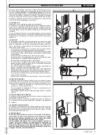
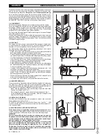
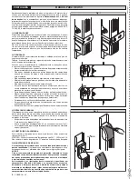
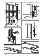
• Access the release knob by sliding its cover C until it stops (Fig.26).
• Rotate the release knob by 90° anticlockwise (Fig.26).
• To restore motor-driven operation, return the knob to its original posi-
tion.
If the garage does not have a secondary access door, an external release
mechanism is provided (Mod. SM1-2) which can be fitted to the door cre-
mone bolt (fig. 27). Such a mechanism can activate the release of one or
two gearmotors.
If the release is fitted on the outside, then the return spring of the release
lever shown in fig. 27 must be loaded.
11) CHECKING THE AUTOMATION
Before considering the automation completely operational, the following
checks must be made with great care:
Check that all components are properly fastened.
Check that all the safety means work properly (i.e. photocells, pneumatic
rubber skirt, etc.).
Check the emergency manoeuvre function.
Check the opening and closing manoeuvres using the controls.
Check the control unit’s electronic logic in normal or customised operation
in the control unit.
12) USE OF THE AUTOMATION
Since the automation may be remote controlled either by radio or a start
button, it is essential that all safety means are checked frequently.
Any malfunction should be corrected immediately by qualified person-
nel.
Keep children at a safe distance from the field of action of the automa-
tion.
13) THE CONTROLS
With the automation the door has a power driven opening and closing. The
controls can come in various forms (i.e. manual, remote controlled, limited
access by magnetic badge, etc.) depending on needs and installation
characteristics. For details on the various command systems, consult the
specific instruction booklets.
Anyone using the automation must be instructed on its operation and
controls.
14) MAINTENANCE
All maintenance operations must be performed with the system power
supply shut off.
The actuator does not require periodical maintenance operations. If neces-
sary, check that the screws are properly tightened and that the telescopic
arms are adequately greased.
Check the safety devices of the door and motor drive.
Check the pushing force periodically. If necessary, adjust the position of the
electric torque in the control unit.
For any malfunction that remains unsolved, shut off the power to the system
and call a qualified specialist (installer). When the automation is out of order,
activate the manual release to allow manual opening and closing.
15) TROUBLESHOOTING
15.1) Faulty operation of the gearmotor
Use a suitable instrument to check if there is a voltage across the gearmotor
terminals when an open or close command has been given.
If the motor vibrates but does not turn, this may be due to:
the common wire C is wrongly connected (it is always light blue) the drive
capacitor is not connected to the terminals in the control unit if the leaf
moves in the wrong direction, invert the drive connections of the motor in
the control unit
LEAF STOP: the door may not complete its stroke or the motor may continue
to run after the door has reached the stop position. Check the position of the
cams controlling the limit switches.
15.2) Faulty operation of the electrical accessories
If any of the control and safety components are faulty, this can cause mal-
functions or a breakdown of the whole automation.
In case of a fault, it is wise to disconnect each of the components in the
automation one at a time, until the one that is causing the fault is found.
After having repaired or replaced it, restore all the components that were
disconnected. For details on each component, refer to its specific instruc-
tion manual.
16) NOISE
The aerial noise produced by the gearmotor under normal operating condi-
tions is constant and does not exceed 70dB(A).
17) SCRAPPING
Materials must be disposed of in conformity with the current regulations.
In case of scrapping, the automation devices do not entail any particular
risks or danger. In case of recovered materials, these should be sorted out
by type (electrical components, copper, aluminium, plastic etc.).
18) DISMANTLING
When the automation system is disassembled to be reassembled on another
site, proceed as follows:
• Disconnect the power supply and the entire electrical installation.
• Remove the gearmotor from its fixing base.
• Disassemble the control panel, if separate, and all installation compo-
nents.
• In the case where some of the components cannot be removed or are
damaged, they must be replaced.
WARNINGS
Correct controller operation is only ensured when the data contained
in the present manual are observed. The company is not to be held
responsible for any damage resulting from failure to observe
the installation standards and the instructions contained in the
present manual.
The descriptions and illustrations contained in the present manual are
not binding. The Company reserves the right to make any alterations
deemed appropriate for the technical, manufacturing and commercial
improvement of the product, while leaving the essential product
features unchanged, at any time and without undertaking to update
the present publication.
14 -
PHEBE Ver. 03
D811328_03
D811328_03
D811328_03
D811328_03
Summary of Contents for PHEBE
Page 2: ...2 PHEBE Ver 03 D811328_03 D811328_03 D811328_03 D811328_03...
Page 32: ......


