INSTALLATION MANUAL
ENGLISH
smoothly and the pushing or pulling force will fluctuate during its stroke.
To respect the opening speed and ensure the controller operates correctly,
it is best to keep the difference between “a” and “b” as low as possible.
The table has been worked out for a 40-mm thick medium-size gate.
Always check that there is no possible collision between the gate and
the operator.
4.3) Off-standard installations.
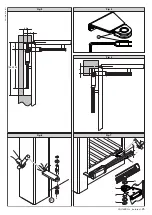
Fig. 3 shows an installation with a recess when there is not sufficient
space between the leaf and perimeter wall.
When the leaf position does not provide for a value of “b” present in the table,
change the length of the bracket or make a recess in the gate-post (Fig. 3).
4.4) Anchoring the attachments to the gate-post.
Fix the bracket “P” (fig. 6) to the gate-post with a good welding.
In the same way, weld the “F” bracket to the gate (or fix the bracket with 2
M8 screws and 2 wide washers
), making sure that the operator to be fitted
is positioned parallel with the gate movement plane, fig.7. The bracket
“F” should be welded in the same way to the gate taking care that the
actuator can then be mounted perfectly horizontal to the line of travel of
the gate fig. 7.
• If the gate-post is in brick, the plate “PF” must be set soundly into the post
using adequately sized cramps “Z” welded to the back of the plate (fig. 8).
• If the gate-port is in stone and the gate is small, the plate “PF” can be
mounted with four metal expansion plugs “T” (fig. 9). If a larger gate is
being installed it would be better to use a corner plate “PF” (fig. 10).
Fit the rear bracket pin as in Fig.6.
4.5) Anchoring the attachments to the gate leaf.
Fixing bracket “F” must be fixed at a distance of 825 mm from attachment
P in Fig.6.
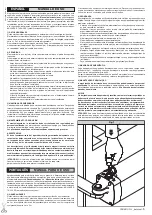
IMPORTANT: the front bracket must be fitted with the bush collar
protruding UPWARDS (Fig.4 Ref.A).
4.6)
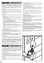
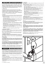
Power supply cable (Fig.12)
The board power supply cable must be of the H 05 RN-F type or equivalent.
The equivalent cable must guarantee:
- permanent outside use
- rated voltage of 300/500 V
- maximum temperature on the cable surface of +50° C
- minimum temperature of -25° C
Moreover, it must have a minimum section of 4 x 0,75 mm
2
and, for the
cable to hold correctly, it must be provided with an external sheath of Ø =
7.1 to 9.6 mm. Insert the cable into O ring “K” (Fig.12), strip it by about 40
mm and connect the cables to the terminal bar (see diagram S).
The wiring of the terminal board must be carried out as shown in Fig. 12-
diagram S:
M1
= operation 1
M2
= operation 2
= earthing
N
= common
Position the cable sheath so that O ring “K” is inserted in its housing in
the base and, leaving the sheath protrude by about J=5 mm (as shown
in Fig.12), close the hatch and fix it by means of the 3 screws.
4.7) Operator fitting
Position the operator on the brackets and fix everything as indicated in
Fig. 6 and 7.
In the case of gates moving over a slope (opening towards the inside with
an upward sloping driveway), the operator allows the gate to oscillate with
respect to the horizontal axis, for the maximum values indicated in fig.7.
5) GROUND GATE STOPS
For the controller to operate correctly the gate stop “FA” must be used both
in opening and closing, as shown in fig. 11.
6) THE ELECTRICAL PLANT SET-UP
Lay out the electrical installation (fig. 13) with reference to the national
standards in force for electrical installation.
The mains power supply connections must be kept totally separate from the
service connections (photocells, electric edges, control devices etc.).
Connect the control and safety devices in compliance with the previously
mentioned electrical installation standards.
Fig.13 shows the number of connections and the cross section for power
supply cables having a length of approximately 100 metres; in case of longer
cables, calculate the cross section for the true automation load.
When the auxiliary connections exceed 50-metre lengths or go through
critical disturbance areas, it is recommended to decouple the control and
safety devices by means of suitable relays.
The main automation components are (fig.13):
I
Type-approved omnipolar circuit breaker with at least 3 mm. contact
opening, provided with protection against overloads and short circuits,
suitable for cutting out automation from the mains. If not already instal-
led, place a type-approved differential switch with a 0.03A threshold
in the circuit just before the automation system.
Qr
Control panel and incorporated receiver.
S
Key selector
AL
Blinker tuned in with antenna
M
Controller
E
Electric lock
Fte
Pair of outside photocells (transmitters)
Fre
Pair of outside photocells (receivers)
Fti
Pair of inside photocells with column (transmitters)
Fri
Pair of inside photocells with column (receivers)
T
1-2-4 channel transmitter
RG58
Antenna cable
All metal masses in the housings of equipment and automation must be
earthed.
Warning!
For actuator wiring and accessory connection, refer to the relevant
instruction manuals. The control panels and accessories must be suitable
for use and conform to current standards.
Should the opening or closing direction be incorrect, it is possible to invert
the connections of operation 1 and operation 2 on the control board.
The first command after an interruption of the power supply should be an
opening manoeuvre.
7) ADJUSTING THE PUSHING FORCE
WARNING: Check that the impact force value measured at the
points established by the EN 12445 standard is lower than that
specified in the EN 12453 standard.
The pushing force is calibrated by means of the torque regulator in the
control unit. The optimum torque must allow a complete opening or closing
cycle with the minimum force necessary. An excessive torque can reduce
the anti-crush safety. In the other case, an insufficient torque can impede
the manoeuvres. Consult the control unit’s instruction manual.
8) ADJUSTMENT OF THE LIMITING DEVICES
The correct adjustment of the limiting devices is obtained by setting the
working time on the control board correctly. Refer to the instructions of the
control board.
WARNING!! It is very important to check that:
1) with the leaf completely closed, a safety gap of at least 12mm is left
between the nut screw and the contour closing cap (Fig. 16).
2) with the leaf completely open, a safety gap of at least 12mm is left
between the nut screw and the operator cover (Fig. 17).
9) MANUAL OPENING
All controllers feature a key release mechanism. After lifting the lock cover
(fig.14), insert the release key supplied and turn it clockwise by 90°.
Push the leaf manually to open the gate. To reset the motorised operation,
turn the key in the opposite direction and refit the cover.
10) ELECTRIC LOCK
WARNING: In the case of leaves over 3m long, it is indispensa
ble to install an electric lock.
11) CHECKING THE AUTOMATION
Before considering the automation completely operational, the following
checks must be made with great care:
• Check that all the components are firmly anchored.
• Control all the safeties work properly (i.e. photocells, pneumatic skirt,
etc.).
• Check the emergency manoeuvre control.
• Check the opening and closing manoeuvres using the controls.
• Check the control unit’s electronic logic in normal (or customised) ope-
ration.
10 -
PHOBOS N L _beta test
D811609_beta test

