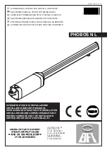
INSTALLATION MANUAL
ENGLISH
Thank you for buying this product, our company is sure that you will be more
than satisfied with the product’s performance. The product is supplied with
a “
Warnings
” leaflet and an “
Instruction booklet
”. These should both be
read carefully as they provide important information about safety, installa-
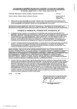
tion, operation and maintenance. This product complies with the recognised
technical standards and safety regulations. We declare that this product
is in conformity with the following European Directives: 89/336/EEC and
73/23/EEC (and subsequent amendments).
1) GENERAL SAFETY
WARNING! An incorrect installation or improper use of the product
can cause damage to persons, animals or things.
• The “
Warnings
” leaflet and “
Instruction booklet
” supplied with this
product should be read carefully as they provide important information
about safety, installation, use and maintenance.
• Scrap packing materials (plastic, cardboard, polystyrene etc) according
to the provisions set out by current standards. Keep nylon or polystyrene
bags out of children’s reach.
• Keep the instructions together with the technical brochure for future
reference.
• This product was exclusively designed and manufactured for the use
specified in the present documentation. Any other use not specified
in this documentation could damage the product and be dangerous.
• The Company declines all responsibility for any consequences resulting
from improper use of the product, or use which is different from that
expected and specified in the present documentation.
• Do not install the product in explosive atmosphere.
• The construction components of this product must comply with the
following European Directives: 89/336/CEE, 73/23/EEC, 98/37/EEC
and subsequent amendments. As for all non-EEC countries, the above-
mentioned standards as well as the current national standards should
be respected in order to achieve a good safety level.
• The Company declines all responsibility for any consequences result-
ing from failure to observe Good Technical Practice when constructing
closing structures (door, gates etc.), as well as from any deformation
which might occur during use.
• The installation must comply with the provisions set out by the follow-
ing European Directives: 89/336/CEE, 73/23/EEC, 98/37/EEC and
subsequent amendments.
• Disconnect the electrical power supply before carrying out any work
on the installation. Also disconnect any buffer batteries, if fitted.
• Fit an omnipolar or magnetothermal switch on the mains power supply,
having a contact opening distance equal to or greater than 3 mm.
• Check that a differential switch with a 0.03A threshold is fitted just
before the power supply mains.
• Check that earthing is carried out correctly: connect all metal parts for
closure (doors, gates etc.) and all system components provided with
an earth terminal.
• Fit all the safety devices (photocells, electric edges etc.) which are
needed to protect the area from any danger caused by squashing,
conveying and shearing.
• Position at least one luminous signal indication device (blinker) where
it can be easily seen, and fix a Warning sign to the structure.
• The Company declines all responsibility with respect to the automation
safety and correct operation when other manufacturers’ components
are used.
• Only use original parts for any maintenance or repair operation.
• Do not modify the automation components, unless explicitly authorised
by the company.
• Instruct the product user about the control systems provided and the
manual opening operation in case of emergency.
• Do not allow persons or children to remain in the automation operation
area.
• Keep radio control or other control devices out of children’s reach, in
order to avoid unintentional automation activation.
• The user must avoid any attempt to carry out work or repair on the
automation system, and always request the assistance of qualified
personnel.
• Anything which is not expressly provided for in the present instructions,
is not allow.
• Installation must be carried out using the safety devices and controls
prescribed by the EN 12978 Standard.
• Check that the stated temperature range is compatible with the place
where the operator is to be installed.
• If present, the hold button (hold-to-run control) must be fitted within
sight of the door but away from the moving parts, at a height of 1.5 m,
and must not be accessible to the public.
• If the operator is fitted at a height lower than 2.5 m, you must guarantee
an adequate degree of protection for the electrical and mechanical
parts.
• Make sure that squashing is avoided between the moving parts and
surrounding fixed parts. Fit all the safety devices (photocells, safety
edges etc.) required to protect the area from any danger of squashing,
drawing in and shearing.
• After completing the installation, ensure that the motor is set correctly
and that the protection and release systems operate correctly.
2) GENERAL OUTLINE
Electromechanical operator designed to automate residential-type gates.
The gearmotor keeps the gate blocked on closing and on opening, without
needing an electric lock for leaves up to 3 m long.
For leaves ranging from 3m to 5m long, the electric lock becomes indi-
spensable
The operator has no mechanical clutch. It must be controlled by an electronic
control panel provided with torque setting. The end-of-stroke operation is
managed by the control panel.
3) TECHNICAL SPECIFICATIONS
Power supply : .....................................single-phase 230V
~
±10% 50 Hz(*)
Motor revolutions : ......................................................................2800 min
-1
Absorbed power : ............................................................................... 210 W
Capacitor : ......................................................................................... 6.3 µF
Absorbed current : ............................................................................... 0.8 A
Insulation class : ........................................................................................ F
Thermal protection : .................................................. 110 °C (self-resetting)
Pushing and towing force : ...............................................2000 N (~200 kg)
Speed : .............................................................................. approx. 20 mm/s
Impact reaction : ......................................Electronic clutch on control panel
Manual manoeuvre : .......................................................... CLS release key
No. manoeuvres in 24 hours : ..............................................60 manoeuvres
Maximum leaf length without electric lock : ........................................... 3 m
Maximum leaf length with electric lock: ................................................. 5 m
Maximum leaf weight : ......................................................2500 N (~250 kg)
Environmental conditions : ........................................from -10 °C to + 50 °C
Degree of protection : ..........................................................................IP X4
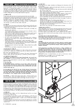
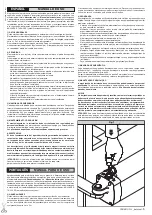
Dimensions : .................................................................................. See fig.1
Operator weight : .....................................................................77N (~7.7kg)
Lubrication : .................................................................... permanent grease
(*) Available in all power supply voltages.
4) INSTALLATION OF THE ACTUATOR
4.1) Preliminary checks
Check that:
• The gate structure is sufficiently sturdy.
• Also make sure that the actuator pushes against the leaf reinforced section.
• The leaves move manually and without effort all along their stroke.
• The door stop plates are fitted at the end of both closing and opening
strokes.
• If the gate has not been recently installed, check the wear condition of all
components.
• Repair or replace faulty or worn parts.
The automation reliability and safety are directly influenced by the state
of the gate structure.
The diagram in fig. 2 should be used as a reference for installation and
consult the table for the distances in mounting the gate post.
The diagram in fig. 2 uses the following legend:
P Gate post rear fastening bracket
F Front leaf fastening bracket
a-b “P” bracket installation value
C Distance between fixing points
D Gate length
X Distance from gate axis to the edge of the post
Z Always over 45 mm (b - X)
kg max. weight of leaf
α
°
leaf opening in degrees
4.2) How to read the installation distance tables (Fig.2)
Select “a” and “b” according to the angle in degrees
α
°
that the gate has to
open. The optimum “a” and “b” values for 92° opening at constant speed are
highlighted.
If there is too large a difference between “a” and “b”, the leaf will not travel
PHOBOS N L _beta test -
9
D811609_beta test

