SW-Stahl und Werkzeugvertriebs GmbH
Tel. +49 (0) 2191 / 46438-0
F
5 6
e s s a r t S r e s u k r e v e L
ax +49 (0) 2191 / 46438-40
e d . l h a t s w s
@
o f n i : l i a
M - E
d i e h c s
m
e R 7 9 8 2 4 - D
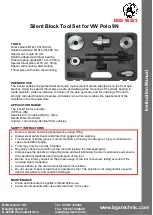
Instruction Manual
BGS technic KG
Bandwirkerstr. 3
D-42929 Wermelskirchen
Tel.: 02196 720480
Fax.: 02196 7204820
mail@bgs-technic.de
www.bgstechnic.com
Note:
The instructions are meant as brief information and do not replace any vehicle-specific service
literature. Please always use appropriate service-literature for repairs, here you will find the tightening
torques and other important information.
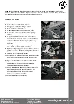
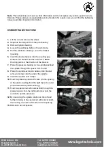
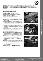
DISMOUNTING INSTRUCTIONS
1.
Lift the car and remove the wheel
2.
Separate the ball joint from the pivot bearing
3.
Dismount plastic bearing
4.
Loosen the wishbone bolts on the sub-frame
5.
Pull the wishbone sideways out of the bracket
mounting
6.
Insert the knurled spacer into the resulting gap
between the bracket and the sub-frame.
Note
:
Knurling points in the direction of the bracket
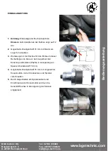
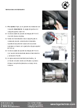
7.
Place the pressure bearing on the spindle and feed
the spindle through the spacer from the left
8.
Place the spindle-extension between the bracket
arms and screw onto the end of the spindle
9.
Insert the spindle until it stops
10.
Feed the pressure piece with collar into the spacing
of the plastic bushing from the right (here the collar
points towards the plastic bushing)
11.
Feed the special nut with conical shaft through the
pressure piece from the right and screw onto the
end of the spindle-extension
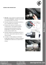
12.
By countering the spindle rotation on the left and
further rotating of the special nut with conical shaft,
the bushing can now be forced out of the spacing
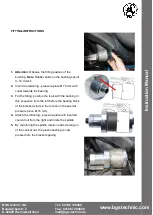
13.
Dismantle all components.


