background image


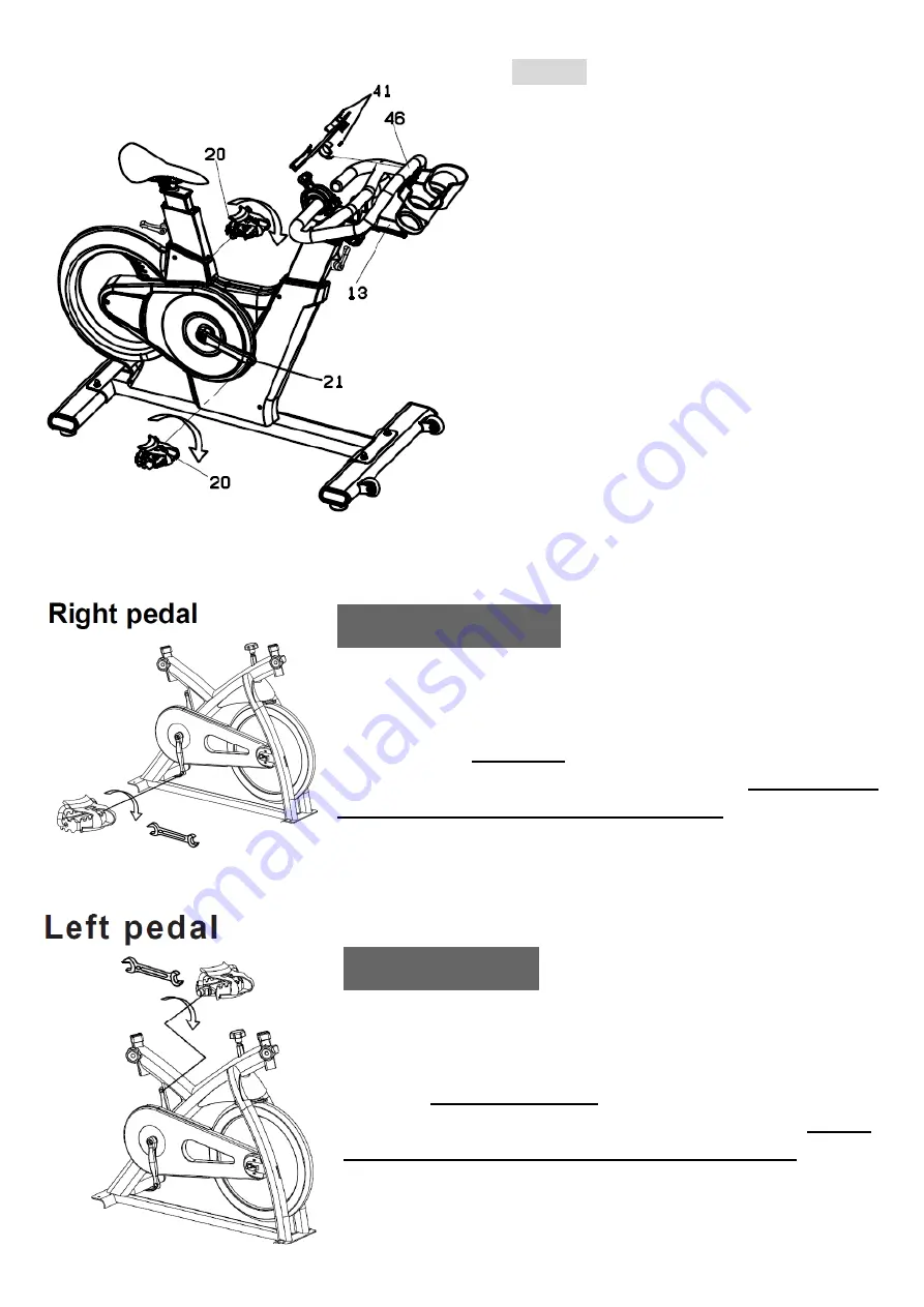
Right Pedal   

Please make sure pedal in your hand is the right pedal before 

Installation. Please refer to the figure. Align the right pedal with 

right crank at 90 degree. Gently insert the pedal in the crank arm. 

Turn the pedals 

clockwise

 as tightly as you can with your hand. 

Use the wrench to ensure it is tightened securely. 

Please always 

tighten by hand first, then finish by wrench.


Left Pedal   

Please make sure pedal in your hand is the left pedal before     

Installation. Please refer to the figure. Align the left pedal with left 

crank at 90 degree. Gently insert the pedal in the crank arm. Turn 

the pedals 

counter- lockwise

 as tightly as you can with your 

hand. Use the wrench to ensure it is tightened securely. 

Please 

always tighten by hand first, then finish by wrench.


STEP 3


Screw the I-PAD bracket (41) onto handle 

bar (46) by clamp which is on the back of 

I-PAD bracket. 


Attach the pedals (20) into the crank arms 

(21), each pedal is marked with L (left) or R 

(right) to denote the side of the spinning bike 

they are on.   

Note 

– the pedal has to work with the 

same side with the crank.


Be careful to 

align the threads correctly to avoid 

damaging them.

 Tighten using a 15mm 

spanner; both pedals should tighten towards 

the front of the spinning bike. 


Summary of Contents for H973

Page 1: ... OWNER S MANUAL H973 H915P ...

Page 2: ...2 ...

Page 3: ...o may cause permanent damage to your body Please verify that all parts associated with this product are in good condition and accounted for During the assembly process please be sure to follow each step accordingly as it has been explained within the manual ...

Page 4: ...ibed in this manual DO NOT use accessories that are not recommended 6 Do not place sharp objects near the machine 7 Any person with physical or coordination limitations should not use the machine without the assistance of a qualified per son or doctor 8 Do not use the machine if it is not working correctly 9 Before using the machine thoroughly inspect the equipment for proper assembly 10 Use only ...

Page 5: ...then insert bolt 30 from bottom Tighten the nut 27 with washer 28 and bolt 30 by the wrench Use the same procedure to install the rear foot tube 31 STEP 2 First please remove the stopper 57 from front end of handle bar post 13 then slip the handlebar 46 into the handlebar post 13 and use adjuster knob 6 to tighten handle bar 46 on handle bar post 13 After it make sure to re screw the stopper 57 on...

Page 6: ...al with left crank at 90 degree Gently insert the pedal in the crank arm Turn the pedals counter lockwise as tightly as you can with your hand Use the wrench to ensure it is tightened securely Please always tighten by hand first then finish by wrench STEP 3 Screw the I PAD bracket 41 onto handle bar 46 by clamp which is on the back of I PAD bracket Attach the pedals 20 into the crank arms 21 each ...

Page 7: ...tighten it with screw Connect the sensor cable 42 which come from the handlebar post 13 with cable on the back of monitor Before riding Securely confirm all of the knobs 6 and release lever 7 saddle 1 Pedals 20 and screws are fastened before your training Stability If the floor is not even you can adjust the height by front foot tube adjuster pad 36 to make it firmly Adjusting the resistance Adjus...

Page 8: ...inding the user adjust the lever to proper direction to prevent interference Please make sure the lever direction as following before your training Lever for Head tube Upward Lever for Seat tube backward MOVING There are moving wheel 11 located in front foot tube for moving the machine ...

Page 9: ...y forwards and backwards until you reach the required position Then securely re tighten the adjuster knob For safety concern there is a stopper on the handlebar post to avoid the handlebar post exceed the area can be fixed Seat adjustment Undo the adjuster release lever located where the seat post fits into the frame Loosen the adjuster release lever to up or down the seat post for the required po...

Page 10: ...10 Exploded Drawing ...

Page 11: ...e PC 12 Tension knob SET 43 Flywheel bearing 6203zz PC 13 5 57 Handlebar post w end cap stoppers PC 44 Flywheel axle set SET 14 Bottle cage PC 45 Flywheel complete SET 14 1 Screw Nut washer for bottle cage SET 46 50 Handlebar w rubber sleeve PC 15 Belt PC 47 Bushing for heard tube PR PR 16 Idler w bearing c clip PC 48 Bushing for seat tube PR PR 17 Bolt and Nut PR 49 Monitor w screw PC 18 Brake pa...

Page 12: ...ar post and clean tube X 7 Remove seat and clean tube X 8 Check security of all knobs and release levers X 9 Check toe straps for signs of wear X 10 Check crank bolts and re tighten X 11 Make sure pedals are screwed in X 12 Check brake pads for wear align and wipe the lubricating oil on it X 13 Check belt tension retighten when loose X 14 Keep flywheel clean Wipe with clean dry fabric to clear dir...

Page 13: ... display will be active to show all data upon pedaling Once pedaling stops LCD will remain blinking displaying latest data before pedaling stopped The display will switch off if pedal stopped over 45 seconds 三 顯示視窗說明 Display data a SPEED 為一正數 其計數設定為 0 在視窗最上方 顯示當下速度 以指標顯示 Start from 0 and plus On Top of the LCD display showing current speed with pointer b TIME 為一正數 其計數設定為 0 時間視窗顯示程式運作的總時間 時間由 00 00...

Page 14: ...顯示使用者所消耗的卡路里 卡路里由 0 向上正數至 999 每次增加 1 卡路里 Start from 0 and plus showing calories consuming of this workout Range 000 0 999 9 f PULSE 當使用者用無線心跳發射器時 可顯示使用者心跳值 顯示範圍 60 240BPM 需搭配 5K 的胸帶 與 Polar 系統相容 For console with HR built in receiver bottom of the LCD showing HR Range 60 240 BPM The chest belt must be 5K and receiver is compatible to polar g Replace the battery 更換電池 Backside up Take the battery cov...

Page 15: ...15 ...

Page 16: ...16 BH Asia Ltd No 80 Zhongshan Rd Daya Dist Taichung City 42841 Taiwan Tel 886 4 2560 9200 Fax 886 4 2560 9280 Email info bhasia com tw ...

Reviews: