background image

 33 

*12

41

28

41

28

41

28

41

28

92

103

88

100%

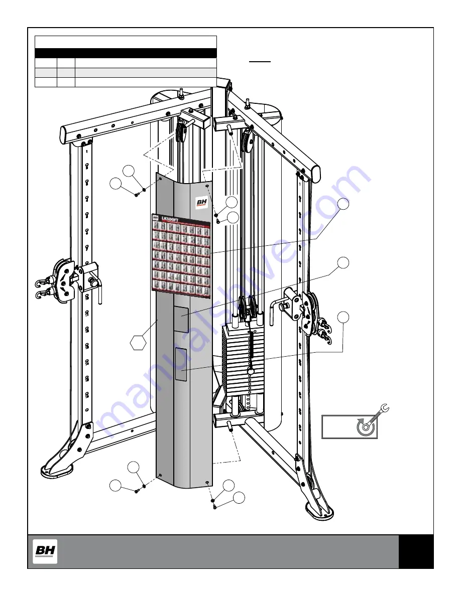
Fully Tighten

Wrench tighten all hardware in this step.

Step 16     Assembly List

Item Qty. Description

28

4

HEX HEAD CAP SCREW GR-5 Z/P 1/4-20 X 3/4

41

4

FLAT WASHER USS Z/P 1/4"

*12

1

FRONT SHROUD ASSEMBLY

Note:

• It is strongly recommended that two people 

participate in this assembly step.

• Some parts have been removed for Clarity.

Summary of Contents for LK500FT

Page 1: ...tructions carefully before using this product Retain this owner s manual for future reference BH North America 20155 Ellipse Foothill Ranch California 92610 p 949 206 0330 f 949 206 0350 www BHFitness...

Page 2: ...ction 03 Warnings and Labels 04 Anchoring the Unit 08 Important Safety Instructions 09 Training Guidelines 10 Suggested Stretches 14 Assembly Instructions 16 Pre assembled Components 36 Parts List 41...

Page 3: ...ect from BH Fitness If you have any questions concerns or product issues please call our Customer Service Team at 1 866 325 2339 or email us at CustomerSupport BHNorthAmerica com Carefully read throug...

Page 4: ...m 88 BHF3150 92 BHF3134 103 BNH2924 98 BHF3135 Recommended BH Parts Use only BH replacement parts when servicing Failure to do so will void warranty on product and could result in personal injury 101...

Page 5: ...5 86 BHF2903 97 BNH3089 93 BNH3089 93 BNH2908 94 BNH2908 94 BNH3146 90 BNH2912 89 BNH2916 91 BNH2916 91 BNH2925 99 BNH2926 102 BHF3147 95...

Page 6: ...LK500FT BH Fitness 20155 Ellipse Foothill Ranch CA 92610 Toll Free 866 325 2339 www BHFitnessUSA com 88 BHF3150 92 BNH3089 93 BNH2908 94 BHF3134 103 BNH3146 90 BNH2912 89 BNH2916 91 BNH2924 98 BNH2925...

Page 7: ...ou from BH Fitness by contacting our service department at Toll Free 866 325 2339 customersupport bhnorthamerica com BHF3135 Recommended BH Parts Use only BH replacement parts when servicing Failure t...

Page 8: ...8 ANCHORING THE UNIT Holes on footplates are provided for anchoring the unit to the floor See anchoring hole locations below ANCHORING HOLE ANCHORING HOLE ANCHORING HOLES BNH3089...

Page 9: ...e Company approved by BH 3 Make sure each machine is set up and operated on a solid level surface Do not install equipment on an uneven surface 4 Provide an adequate safety perimeter between the machi...

Page 10: ...ithout stopping FLEXIBILITY The range of motion of your joints Improving flexibility involves the stretching of muscles and tendons to maintain or increase suppleness and it provides increased resista...

Page 11: ...reate an overload and therefore provide continued improvement SPECIFICS Different forms of exercise produce different results The type of exercise that is carried out is specific to the muscle groups...

Page 12: ...unt 23 22 22 21 20 19 19 18 18 Beats per Minute 138 132 132 126 120 114 114 108 108 PULSE COUNT The pulse count on your wrist or carotid artery in the neck taken with two index fingers is done for ten...

Page 13: ...ill not restrict your movement in any way while exercising Clothes should be light enough to allow the body to cool Excessive clothing that causes you to perspire more than you normally would gives yo...

Page 14: ...r one count Then lift your right shoulder up for one count as you lower your left shoulder Side Stretches Open your arms to the side and continue lifting them until they are over your head Reach your...

Page 15: ...d hold for 15 counts Hamstring Stretches Sit with your right leg extended Rest the soles of your left foot against your right inner thigh Stretch toward your toes as far as possible Hold for 15 counts...

Page 16: ...16 ASSEMBLY INSTRUCTIONS...

Page 17: ...LLEY WIDE GROOVE 3 8 X 1 X 3 1 2 25 4 FLANGED SPACER Z P 3 8 X 16 5MM 31 2 HEX HEAD CAP SCREW GR 5 Z P 3 8 16 X 2 9 16 44 2 NYLON INSERT THIN PATTERN LOCK NUT Z P 3 8 16 2 1 BASE FRAME LEFT SIDE ASSEM...

Page 18: ...ASHER SAE Z P 3 8 44 1 NYLON INSERT THIN PATTERN LOCK NUT Z P 3 8 16 1 1 REAR UPRIGHT ASSEMBLY 2 1 BASE FRAME LEFT SIDE ASSEMBLY 3 1 BASE FRAME RIGHT SIDE ASSEMBLY Note It is strongly recommended that...

Page 19: ...Qty Description 4 2 SELECTOR POST 13 1 CARRIAGE RT 14 1 CARRIAGE LT 4 4 13 14 Note Position reference numbers facing toward the inside of the unit Note It is strongly recommended that two people parti...

Page 20: ...ome component s may need pre assem bly and or alignment during the assembly process Step 4 Assembly List Item Qty Description 4 2 SELECTOR POST 26 2 NYLON SPACER 3 8 X 7 8 X 3 8 31 2 HEX HEAD CAP SCRE...

Page 21: ...Assembly List Item Qty Description 20 2 BLACK NYLON PULLEY WIDE GROOVE 3 8 X 1 X 3 1 2 32 2 HEX HEAD CAP SCREW GR 5 Z P 3 8 16 X 2 1 2 38 2 SPLIT LOCK WASHER Z P 1 2 40 2 ARC WASHER SAE Z P 1 2 42 2...

Page 22: ...ly process Note It is strongly recommended that two people participate in this assembly step Some parts have been removed for Clarity Step 6 Assembly List Item Qty Description 30 4 HEX HEAD CAP SCREW...

Page 23: ...mbly and or alignment during the assembly process Note It is strongly recommended that two people participate in this assembly step Some parts have been removed for Clarity Step 7 Assembly List Item Q...

Page 24: ...4 HEX HEAD CAP SCREW GR 5 Z P 3 8 16 X 2 3 4 39 4 SPLIT LOCK WASHER Z P 3 8 43 4 FLAT WASHER SAE Z P 3 8 15 2 10 LB TOP PLATE W ADJ SLTR BAR 19 BLK WTS ASSY 51 28 10 LB STEEL WEIGHT PLATE BLK 4 9 16...

Page 25: ...cipate in this assembly step Some parts have been removed for Clarity Step 8 200 lbs Wt Stacks Assembly List Item Qty Description 10 4 GUIDE ROD 19 4 RUBBER DONUT 3 4 X 2 1 2 33 4 HEX HEAD CAP SCREW G...

Page 26: ...the last weight plate and slowly press into place 5 Gently remove application tape and rub each label firmly against the weight stack 6 Once this is complete repeat this procedure for Top Plate label...

Page 27: ...YLON PULLEY WIDE GROOVE 3 8 X 1 X 3 1 2 27 1 CABLE CDP 300 32 2 HEX HEAD CAP SCREW GR 5 Z P 3 8 16 X 2 1 2 43 4 FLAT WASHER SAE Z P 3 8 44 2 NYLON INSERT THIN PATTERN LOCK NUT Z P 3 8 16 64 1 CABLE ST...

Page 28: ...ep 11 Assembly List Item Qty Description 20 1 BLACK NYLON PULLEY WIDE GROOVE 3 8 X 1 X 3 1 2 27 1 CABLE CDP 300 32 1 HEX HEAD CAP SCREW GR 5 Z P 3 8 16 X 2 1 2 43 2 FLAT WASHER SAE Z P 3 8 44 1 NYLON...

Page 29: ...ty Description 20 2 BLACK NYLON PULLEY WIDE GROOVE 3 8 X 1 X 3 1 2 27 1 CABLE CDP 300 32 2 HEX HEAD CAP SCREW GR 5 Z P 3 8 16 X 2 1 2 43 4 FLAT WASHER SAE Z P 3 8 44 2 NYLON INSERT THIN PATTERN LOCK N...

Page 30: ...3 8 16 X 2 1 2 43 2 FLAT WASHER SAE Z P 3 8 44 1 NYLON INSERT THIN PATTERN LOCK NUT Z P 3 8 16 64 1 CABLE STOPPER SHELL 1 1 2 X 1 3 4 65 1 7 8 RD X 1 5 8 LINK 1 8 CABLE 66 1 OVAL HEAD SCREW Z P 10 32...

Page 31: ...h tighten ALL hardware assemblies specially those left loosely fasten making sure the unit is assembled square and perpendicular 100 Fully Tighten Note It is strongly recommended that two people parti...

Page 32: ...Step 15 Assembly List Item Qty Description 28 8 HEX HEAD CAP SCREW GR 5 Z P 1 4 20 X 3 4 41 8 FLAT WASHER USS Z P 1 4 11 1 REAR SHROUD LEFT SIDE ASSEMBLY 46 1 REAR SHROUD RIGHT SIDE ASSEMBLY Note It...

Page 33: ...re in this step Step 16 Assembly List Item Qty Description 28 4 HEX HEAD CAP SCREW GR 5 Z P 1 4 20 X 3 4 41 4 FLAT WASHER USS Z P 1 4 12 1 FRONT SHROUD ASSEMBLY Note It is strongly recommended that tw...

Page 34: ...3 8 16 X 3 1 2 43 4 FLAT WASHER SAE Z P 3 8 44 2 NYLON INSERT THIN PATTERN LOCK NUT Z P 3 8 16 9 1 ACCESSORY HOLDER TUBE 100 Fully Tighten Wrench tighten all hardware in this step Note It is strongly...

Page 35: ...1 22 67 67 Step 18 Assembly List Item Qty Description 21 1 NYLON ANKLE STRAP 22 1 LOW ROW BAR 1 1 4 ALUMINUM 23 1 SQUAT BAR 46 DOUBLE LINK TUBULAR 24 2 CONTOUR ERGO HANDLE LONG STRAP 67 2 SNAP LINK Z...

Page 36: ...2 93 79 70 83 3 52 52 95 93 79 83 70 5 96 98 70 83 CABLE FISHING STRING TO FACILITATE ROUTING THE CABLE 6 52 52 6 98 96 70 83 CABLE FISHING STRING TO FACILITATE ROUTING THE CABLE 3 PRE ASSEMBLED COMP...

Page 37: ...BH repla ceme nt parts Failur e to do so will void warra nty and could result in seriou s injury or death Recommended BH Parts Use only BH replac ement parts when servici ng Failure to do so will void...

Page 38: ...78 62 82 58 62 82 47 43 59 43 20 20 54 43 44 43 60 63 56 43 44 84 76 14 90 94 89 81 63 69 63 69 63 63 69 63 63 69 63 56 89 81 76 90 94 13 84 56 43 44 63 60 44 43 43 20 54 20 43 59 43 47 63 78 62 82 58...

Page 39: ...39 72 97 53 57 53 57 53 57 53 57 72 9 1 74 93 79 73 9 1...

Page 40: ...40 7 44 43 43 30 55 61 43 49 55 50 55 49 43 44 68 99 15 68 68 16 102 68 45 38 77 51 68 71 71 71 71 8 66 67 65 64 66 27 67 65 64 15 7 51 27 8...

Page 41: ...Cable cdp 300 UP8078 2 83 U style tapped hole nut 1 4 20 BNH0708 4 28 Hex head cap screw gr 5 z p 1 4 20 x 3 4 BNH2106 12 84 Yellow grip 1 2 x 4 BNH3059 2 29 Hex head cap screw gr 5 z p 3 8 16 x 1 BNH...

Page 42: ...de assembly UP8066X1 1 12 Front shroud assembly UP8076X1 1 3 Base frame right side assembly UP8067X1 1 13 Carriage left side assembly UP7686X1 1 5 Top frame left side assembly UP8068X1 1 14 Carriage r...

Page 43: ...stead seek service from an authorized service center However you may clean the outer surface Use a soft cloth dampened with warm water Do not use aerosol sprays or pump bottles as they may deposit sed...

Page 44: ...MERS OR PURCHASER FROM SUCH DAMAGE This written warranty is the final complete and exclusive agreement of the parties with respect to the quality or performance of the equipment and no action for brea...

Reviews: