MOD. BU1000BM
15
Move the lower tray (7) up, attach the upper tray (6)
and fix the trays using the joints (18-9) and the screws
(18-6), (18-7), Fig.10.
6. INSTRUCTIONS FOR FITTING THE
SADDLE.-
Take the seat post for the saddle and attach the
saddle (11) to it, Fig.11, tighten the nuts.
Attach the saddle covers (15), (16) using the screws
(18-10), Fig.12.
VERTICAL ADJUSTMENT
.
To raise or lower the seat post, pull the knob (1-54),
Fig.14. and without releasing it, move the seat post.
When it is at the proper height, release the knob.
7. ATTACHING THE PEDALS.-
The assembly instructions for the pedals must be
followed to the letter, fitting these incorrectly could
damage the screw thread on the pedal or the crank.
Right and left refer to the position that the user adopts
when sitting on the saddle to do the exercises.
The right-hand pedal, marked with the letter (R),
screws onto the right-hand crank (Q), also marked
with an (R), in a clockwise direction. Tighten securely,
Fig.13.
The left-hand pedal, marked with the letter (L), screws
onto the left-hand crank, also marked with an (L), in
an anti-clockwise direction. Tighten securely Fig.13.
LEVELLING.-
Once the unit has been placed into its final position,
make sure that it sits flat on the floor and that it is
level. This is achieved by screwing the adjustable foot
(2-11) up or down, Fig.15.
MOVEMENT & STORAGE
.-
The unit is equipped with wheels (2-3) to make it
easier to move about. The two wheels at the front of
the unit make it easier to place the unit in any chosen
position, as shown in the Fig.16. Store it in a dry
place, preferably not subject to changes in
temperature.
MAINS CONNECTION.-
Insert the jack (m) on the transformer (75) into the
connection hole on the main body (1) (bottom, rear of
the machine) and then plug the transformer into a 220
V mains supply, Fig.17.
SEAT POST ADJUSTMENT.-
To adjust the looseness of the seat post, first remove
the two screws of the cover (Fig.18-1.) to access the
seat post. Then tighten the screws of the seat post
with the help of a 3mm Allen key until the lateral
looseness of the seat post is removed (Fig.18-2.).
Check that the seat post can move up and down. Refit
the cover and the two screws.
WIRE FIXING.-
To fix the connection of the antenna and internet
wires, Fig.19, use a screwdriver to open the clamp.
Insert the wire into the clamp and tighten the screw
again, Fig.19.
Do not hesitate to get touch with the Technical
Assistance Service if you have any queries by
phoning customer services (see last page in manual).
BH RESERVES THE RIGHT TO MODIFY THE
SPECIFICATIONS OF ITS PRODUCTS WITHOUT
PRIOR NOTICE
Summary of Contents for SmartFocus BU1000
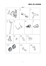
Page 2: ...MOD BU1000BM 2 Fig 1...
Page 3: ...MOD BU1000BM 3...
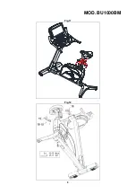
Page 4: ...MOD BU1000BM 4 Fig 2 Fig 3...
Page 5: ...MOD BU1000BM 5 Fig 4 Fig 5...
Page 6: ...MOD BU1000BM 6 Fig 6 Fig 7 Fig 8...
Page 7: ...MOD BU1000BM 7 Fig 9 Fig 10...
Page 8: ...MOD BU1000BM 8 Fig 11 Fig 12...
Page 9: ...MOD BU1000BM 9 Fig 13 Fig 14...
Page 10: ...MOD BU1000BM 10 Fig 15 Fig 16 Fig 17 Fig 18...
Page 11: ...MOD BU1000BM 11 Fig 19...


