10
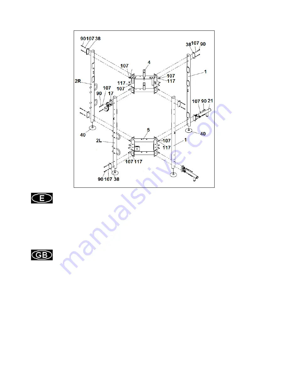
Fig.1
INSTRUCCIONES DE MONTAJE.-
Apoye en el suelo el soporte principal (5).
Coloque en las barras laterales (1), (2R), (2L) los tacos de apoyo (40) y atorníllelos con los tornillos junto
con las arandelas y las tuercas suministrados en los tacos (40).
Coloque en las barras laterales (1), (2R), (2L) las pletinas (38), la polea superior (17) y los soportes
barra (21) y atorníllelos con los tornillos (90) junto con las arandelas (107) y tuercas (117) tal como se
muestra en la figura 1 al soporte inferior (5) y al soporte superior (4).
INSTRUCTIONS FOR ASSEMBLY.-
Rest on the floor the main support (5). Place in lateral bars (1), (2R), (2L) the adjusting pads (40) and
tighten the screws with washers and nuts provided inside the pads (40).Place the lateral bars (1), (2R),
(2L) the plates (38), the upper pulley (17) and the fixed frames (21) and tighten the screws (90) with
washers (107) and nuts (117) as shown in Fig 1 to the main support (5) and upper support (4).
Summary of Contents for L360FS
Page 1: ...L360FS Instrucciones de montaje y utilización Instructions for assembly and use ...
Page 5: ...8 1 9 2 10 2 11 2 13 1 14 1 15 1 16 1 ...
Page 6: ...17 1 20 4 21 2 28 1 29 2 30 1 ...
Page 7: ...31 1 32 1 34 8 36 2 38 5 39 4 40 6 41 7 ...
Page 8: ...42 8 43 4 44 8 48 1 81 7 ...
Page 21: ...L360FS ...


