background image

Operating the Ministand 


13

Battery Pack 

The battery pack is medically approved 
according to IEC 60601-1, CAN/CSA-C22-2, 
No.601-1 M90 and UL 2601-1. 
 
The battery pack assembly is two 12 volt,      
5 Ah (24 volt capacity) fuse protected 
batteries, delivering up to 100 lifts per charge 
(200 lbs or 90 kg). 
 
Battery life is variable (2-3 years) and is 
influenced by proper charging practices and 
load exertion. 

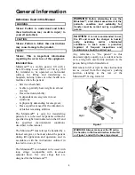
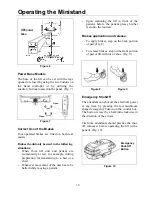
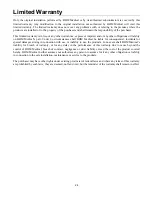
Removable Battery Pack 

The removable battery pack reduces the time 
your lift is out of service because of a 
discharged battery.  
 
To remove discharged battery pack, use both 
hands, grasp the battery pack by the handles 
and at the same time, push the two latch 
buttons located on each side of the battery 
pack, and pull straight out towards you. 
Replace the pack with a fully charged one 
(second battery pack not included) from the 
wall mounted charging unit (not included). 
(Fig 11) 


Figure 11 


NOTE: to ensure long battery life charge for 
a minimum of 8 hours before using the lift 
for the first time.


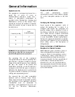
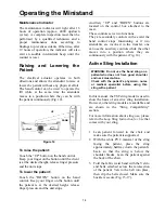
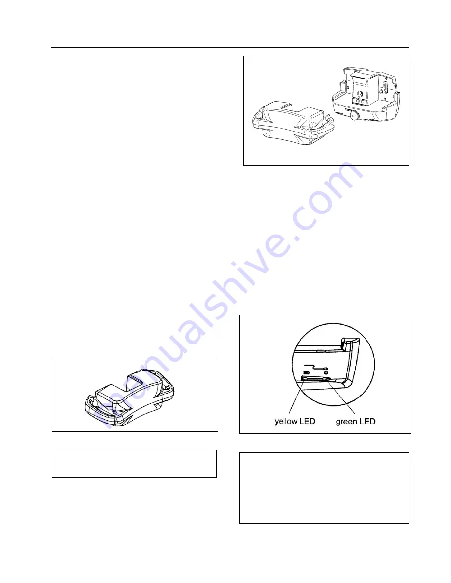
Charging the Battery 

Plug the charger into a wall socket compatible 
with universal voltage input of 90 V up to 240 
V. (Fig. 12) 


Figure 12 


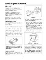
The charger has two LED indicators; yellow 
and green. Their significance is: 


Green light “ON” with no battery pack 
inserted: indicates the charger is on and 
ready for use. 


Green & Yellow light “ON”: indicates the 
battery pack is being charged.  


Green light “ON”/Yellow light “OFF” 
with battery pack inserted: indicates pack 
in the charger is fully charged and ready to 
use. (Fig. 13) 


Figure 13 


WARNING: DO NOT operate the charger with 
a damaged cord or if the unit’s housing has 
been damaged.  


DO NOT forcibly bend the power cord or 
place a heavy object on it. This will damage 
the cord and may cause a fire or electrical 
shock.


Charger 

Battery 

Summary of Contents for Ministand

Page 1: ...001 20075 EN rev 6 September 2010 Ministand Instructions for Use...

Page 2: ...e patented or patent pending Our policy is one of continuous development and we therefore reserve the right to make technical alterations without notice The content of this publication may not be copi...

Page 3: ...10 Operating the Ministand 11 Introduction 11 Adjusting the Width of the Legs 11 Power Base Models 12 Correct Use of the Brakes 12 Brakes application and release 12 Emergency Shut Off 12 Battery Pack...

Page 4: ...t to avoid injuries that can be attributed to the use of inadequate parts only parts designated by BHM Medical should be used on equipment and other appliances supplied by BHM Medical Furthermore unau...

Page 5: ...n this manual The Ministand must always be handled by a trained caregiver who must attend the patient during lift application and operation and in accordance with the instructions outlined in this Ins...

Page 6: ...age of the equipment concerned Consumables must be maintained in accordance with published Instructions for Use and the Preventive Maintenance Schedule Equipment Identification The unit s identificati...

Page 7: ...nufacturer This symbol is accompanied by the product s serial number of the manufacturer This symbol indicates separate collection for all batteries as per the WEEE Directive The black bar indicates t...

Page 8: ...atient This mobile patient lift must be operated by a trained attendant Do not attempt to use the lift if you have not been properly trained to do so This patient lift should never be used by patients...

Page 9: ...ry If the maximum load differs between hoist spreader bar and body support unit i e sling then the lowest maximum load must always be used Electric Shock Prevention Read the battery and charger instru...

Page 10: ...Waste of Electronic and Electrical Components as well as local laws and regulations must be followed If not they may explode leak and cause personal injury When returning batteries insulate their ter...

Page 11: ...10 Sling Compatibility For more information about sling use please refer to the documentation that comes with your sling Chest sling 4001C 4001 Total Transfer sling 4000TTC 4000TT Band sling TST X Hy...

Page 12: ...the legs or push it to the far right to open the legs Fig 4 Pedal base The adjustments are made by changing the position of the pedal Press down on the left side of the pedal to close the legs Press d...

Page 13: ...f the unit has to be halted while moving a patient Upon stationing the lift in front of the patient before the patient places his her feet onto the footrest Brakes application and release To apply bra...

Page 14: ...d one second battery pack not included from the wall mounted charging unit not included Fig 11 Figure 11 NOTE to ensure long battery life charge for a minimum of 8 hours before using the lift for the...

Page 15: ...cated on the control box attached to the mast These controls serve two functions They are secondary controls in the event the hand control stops functioning or if two attendants are involved in the tr...

Page 16: ...e sling are correctly installed in the hook Fig 18 If they are not install the loop properly before lifting the patient Figure 18 Ensure the patient s arms are over the sling and that the sling is not...

Page 17: ...in the sling during the transfer 7 Move the patient directly over the point of transfer and lock the wheels on the wheelchair or bed When the patient is positioned against the chair or bed lock the re...

Page 18: ...ith electrical components or internal corrosion If a hot air dryer is used to dry the lift the temperature must not exceed 80 C 176 F Do not use petroleum based solvents or similar since this may dama...

Page 19: ...removed it is imperative that you reinstall all associated safety devices such as cotter pins split rings and lock nuts If one of these devices is defective you must replace it with an original new co...

Page 20: ...en operating the lift Ensure that the footrest is correctly attached to the mast Ensure that the kneepad is in the proper position for the patient Ensure that the kneepad is tightened If the product d...

Page 21: ...TY CHARGER TROUBLE CHECK POWER ON LIGHT ON CHARGER IS NOT LIT CHECK CHARGER IS PLUGGED INTO WALL RECEPTACLE CHARGER IS PLUGGED IN BUT POWER ON LIGHT IS NOT LIT CHECK THAT ELECTRICAL OUTLET HAS POWER Y...

Page 22: ...h IEC 60601 1 WARNING Radio transmitting devices such as mobile telephones two way radios etc should never be used near the Ministand since they can interfere with the function of the lift Cables from...

Page 23: ...Technical Specifications 22 Figure 22...

Page 24: ...r this warranty to be valid the purchaser must present its original proof of purchase at the moment of the claim The defective unit assembly or part must be returned to BHM Medical for inspection The...

Page 25: ...nces shall BHM Medical be liable for consequential incidental or special damages arising in connection with use or inability to use the products In no event shall BHM Medical s liability for breach of...

Page 26: ...001 20075 EN rev 6 September 2010...

Reviews: