background image

5

VI-6 rear Panel cOntrOls
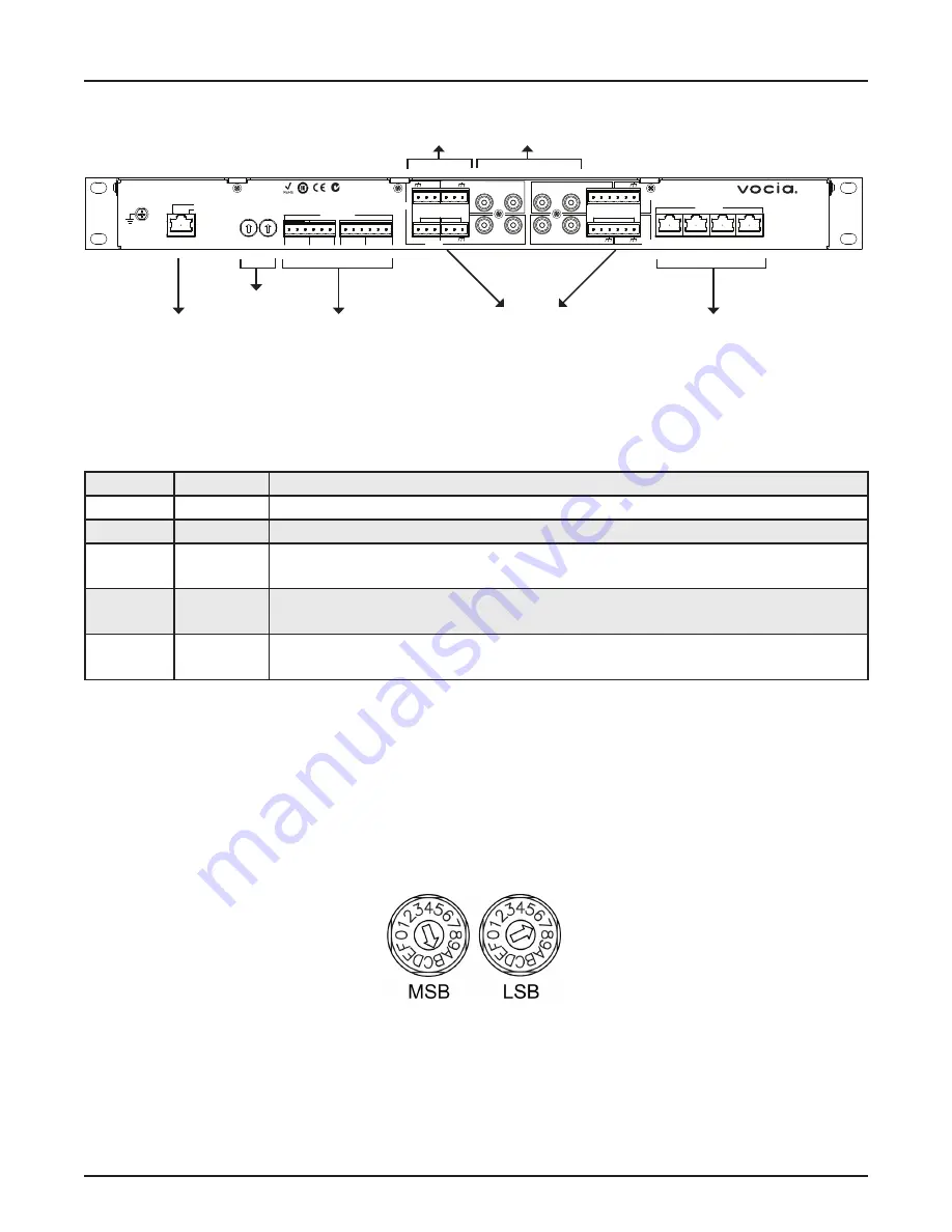
Network Connection

The VI-6 has one RJ45 connector that should wired to standard copper Ethernet cabling to interface the VI-6 to a Vocia system via a poE-
compliant network switch. The RJ45 connector has two LEDs that indicate Ethernet link and network activity (see table below).

Device ID

The rotary ID switches are located on the back of the VI-6 and give the unit a unique Device ID. The switches are in hexadecimal 
format. All VI-6 units must have a unique Device ID to function properly within a Vocia Paging World (i.e., it is not possible to have 

two VI-6 units with the same Device ID of hex 07). To assign a Device ID of hex 07, turn the LSB switch to 7 and leave the mSB 
switch on 0. To create an ID of hex B7, turn the LSB switch to 7 and turn the mSB switch to B. Device ID switches should be set using 
a 0.1 inch (2.5mm) to 0.12 inch (3.0mm) flat blade screwdriver. more information on setting IDs and the hexadecimal numbering 
scheme used in Vocia can be found in the Vocia Help File.

Please note: Changes made to the Device ID while connected to the network require a power cycle in order to take effect. 

CobraNet

The VI-6 is a CobraNet device. All CobraNet routing and bundle assignments are processed by the Vocia devices locally.  
Vocia makes dynamic use of available bundles of CobraNet. Vocia devices are currently not interoperable with non-Vocia devices.  

C   NC NO   C   NC  NO        C   NC NO    C   NC  NO

Paging Ports

1                    2                     3                    4

1                   2                         3                   4

Control Outputs

3     4  10V

(100mA)

L  R

L  R

L  R

L  R

Input 2

Input 4

Input 1

Input 3

Input 5

Input 6

1     2

Model VI-6

-

+

-

+

-

+

-

+

-

+

Control Inputs

Device ID

MSB         LSB

GND

BIAMP SYSTEMS

Designed in Australia

Assembled in USA

YEL:in use/conductor
GRN:link/act

CobraNet

®

PoE IEEE 802.3af

Class 0

N24138

Network 

Connection

Device ID

plug-in Barrier 

Strip Analog 

Inputs

Control 

Inputs

RCA 

Inputs

Control 

Outputs

Not Active

Left LED

Right LED

Description

None

None

No power or data connectivity. please check the poE network connection.

None

Green

Link established.

Flashing 
yellow

Green

Link established and CobraNet activity detected; the unit is acting as a CobraNet performer.

Flashing 
yellow

Flashing 
green

Link established and CobraNet activity detected; the unit is operating as a CobraNet conductor. 

Flashing 
yellow

None

CobraNet fault. Check cabling and configuration for errors.

Summary of Contents for VOCIA VI-6

Page 1: ...Biamp Systems 10074 S W Arctic Drive Beaverton Oregon 97005 U S A 503 641 7287 www biamp com Vocia VI 6 Operation Manual ...

Page 2: ... Setup and Use 4 1 Power Indicator LED 4 2 Signal LEDs 4 3 Control LEDs 4 Rear Panel Controls 5 7 Device ID 5 CobraNet 5 Network Connection 5 Control Outputs 7 Control Inputs 7 Audio Inputs 7 Ground Screw 7 installation 8 specifications block diagram 9 warranty 10 ...

Page 3: ...system the VI 6 meets paging requirements for facilities of all sizes FEATURES Four sets of dual RCA connectors plus terminal block connectors for line level inputs Four control inputs and four control outputs Two microphone line inputs with phantom power Software configurable local audio signal processing including gain filters and compressor limiter Rotary switches for unit identification CobraN...

Page 4: ...ers for the four input channels and are useful for setting optimum signal levels Each LED has four states Please see the table below for the signal mapping to each of the LEDs Detailed metering of current output levels can be obtained in real time via the Vocia software interface 3 Control LEDs The control LEDs signal the current state of the control I Os The first four are input status indicators...

Page 5: ...ce ID while connected to the network require a power cycle in order to take effect CobraNet The VI 6 is a CobraNet device All CobraNet routing and bundle assignments are processed by the Vocia devices locally Vocia makes dynamic use of available bundles of CobraNet Vocia devices are currently not interoperable with non Vocia devices C NC NO C NC NO C NC NO C NC NO Paging Ports 1 2 3 4 1 2 3 4 Cont...

Page 6: ...using shielded CAT5 CAT5e CAT6 or CAT7 cable Ethernet switch with PoE VI 6 VI 6 Ethernet switch without PoE AC Power PoE injector C NC NO C NC NO C NC NO C NC NO Paging Ports 1 2 3 4 1 2 3 4 Control Outputs 3 4 10V 100mA L R L R L R L R Input 2 Input 4 Input 1 Input 3 Input 5 Input 6 1 2 Model VI 6 Control Inputs Device ID MSB LSB GND BIAMP SYSTEMS Designed in Australia Assembled in USA YEL in use...

Page 7: ...l Audio Inputs Two sets of plug in barrier strip and RCA connectors provide analog audio signal input Inputs 1 through 4 are designed for line level input The RCA and plug in barrier strip connectors are resistively summed internally so that a stereo source can be conveniently converted to mono audio Inputs 5 and 6 are designed for microphone or line level inputs and include phantom power All plug...

Page 8: ...nel PVC or nylon washers are appropriate Please install the unit away from heat sources such as vents and radiators and in rooms with adequate ventilation Ensure that air can circulate freely behind beside and above the unit Do not exceed the maximum ambient operating temperature of 113 degrees F 45 C Be aware of conditions in an enclosed rack that may cause the temperature to exceed ambient room ...

Page 9: ...nputs Signal to Noise Ratio 84dB Connection RJ45 with shielded Ethernet PoE cable Cat5 Cat5e Cat6 or Cat7 MicInputsEquivalentInputNoise 126dBu Power 802 3af PoE Class 3 Dynamic Range 100dB Dimensions Height Width Depth 0 75 inches 44 5mm 19 inches 483mm 10 inches 254mm Crosstalk 10kHz 75dB Weight 6 4 lbs 2 9kg Input Impedance Line Inputs Mic Line Inputs 10kΩ 1kΩ Ambient Operating Temperature Range...

Page 10: ...manner that does not comply with BIAMP Systems recommendations 4 Electro mechanical fans electrolytic capacitors gooseneck microphones cords connecting handheld microphones hard drives displays and normal wear and tear of items such as paint knobs handles keypads and covers are not covered under this war ranty All server based devices are warranted for 3 years only 5 This warranty is in lieu of al...

Page 11: ...11 compliance ...

Page 12: ...12 compliance ...

Reviews: