CH – PE – WT100
B-
N
OTE TECNICHE PER L
’
INSTALLAZIONE
/I
NSTRUCTIONS FOR THE ISTALLER
N
OTAS TÉCNICAS PARA LA INSTALACIÒN
/
Edition 07–2003
– 37 –
I
UK
E
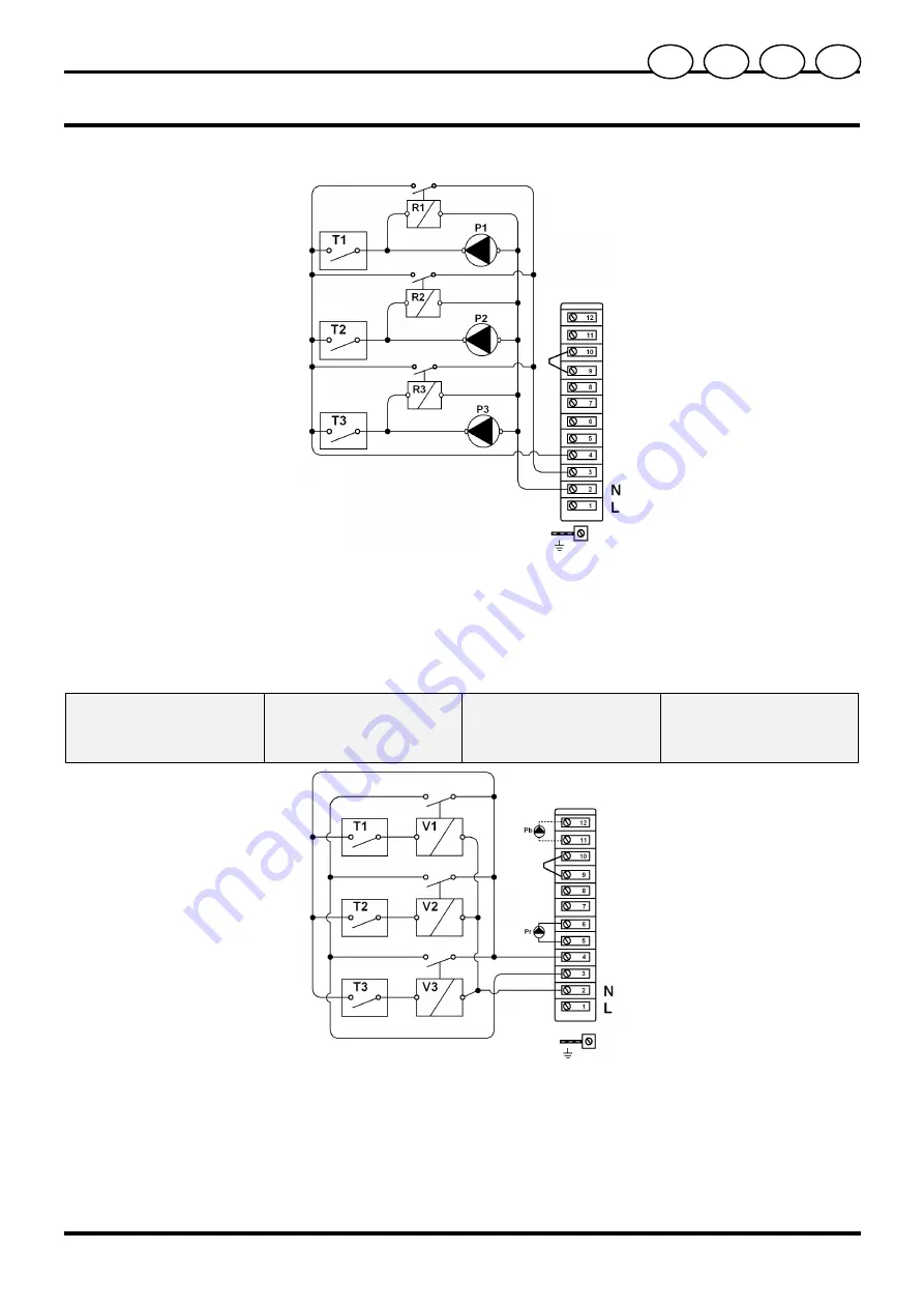
Schema con tre circolatori
(WT100)
Diagram with three
circulators (WT100)
Esquema con tres bombas
de circulación (WT100)
Fig. 6.6C
P
= Circolatore
R
= Relé
T
= Termostato ambiente
P
= Circulator
R
= Relay
T
= Room thermostat
P
= Bomba de circulatión
R
= Relé
T
= Termostato de ambiente
Sconnettere elettricamente il
circolatore riscaldamento della
caldaia scollegando i fili dai
morsetti 5 e 6.
Remove the wires from the
terminals to electrically
disconnect the boiler’s central
heating circulator 5 and 6.
Desconectar eléctricamente la
bomba de circulación para
calefacción de la caldera
desconectando los hilos de los
bornes 5 y 6.
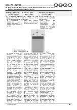
6.7 S
CHEMA ELETTRICO
PER VALVOLE DI
ZONA
6.7 W
IRING DIAGRAM FOR
ZONE VALVES
6.7 E
SQUEMA ELÉCTRICO
PARA VÁLVULAS
ZONALES
Fig. 6.7
V
= Valvola di zona
T
= Termostato ambiente
V
= Zone valve
T
= Room thermostat
V
= Válvula zonal
T
= Termostato de ambiente
Predisporre fra il collettore
mandata e quello di ritorno
riscaldamento un by pass
automatico tarato a 3,5 ÷ 4 metri
Install an automatic by-pass,
calibrated at 3,5 ÷ 4 metres,
between the centar heating
supply and return manifold.
Disponer entre el colector de
alimentación y el de retorno de la
calefacción un by pass
automático ajustado a 3,5 ÷ 4
metros.
Summary of Contents for 25 CH
Page 2: ......


