- 41 -
INST
ALLA
TION
INSTALLATION
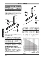
Additional bends at 45° or 90° (Fig. 6.6 C)
Coaxial bends Ø 60/100 mm.
These bends when used with the pipe reduce
the maximum length of the flue pipe by:
For the bend of 45° loss
0.5 m
For the bend of 90° loss
1 m
Exhaust intake split pipes kit Ø 80 mm -
(Fig. 6.7) - (Fig. 6.8)
This kit allows the flue exhaust to be separat
-
ed from the air intake.
Split pipes kit Ø 80 mm
Minimum length
0.5 m
Maximum length (a + b)
40 m
N.B: The air intake and the flue outlet must
not terminate on opposite sides of the
building (EN 483).
Fig. 6.7
Type C
13
Bends of Ø 80 mm at 90° and at 45° are avail
-
able that reduce the maximum total length of
the pipes by:
For the bend of 45° loss
0.9 m
For the bend of 90° loss
1.65 m
Fig. 6.8
90°
45°
Type C
53
Roof flue exhaust kit (Fig. 6.9)
This kit exhausts directly to the roof.
Coaxial pipe
Ø 60/100
mm
Ø 80/125
mm
Nominal height
0.96 m
0.96 m
Maximum height
10 m
10 m
Fig. 6.9
45°
90°
Type C
33
600 mm
600 mm
Extensions are available for reaching the
maximum height.
Bends at 90° and at 45° are available that re
-
duce the maximum total length of the pipes
by:
For the bend of 45° loss
0.5 m
For the bend of 90° loss
1 m
Pluming kit A (Fig. 6.10)
Coaxial Ø 60/100 mm + vertical part Ø 60 mm
(flue outlet).

